Finite element compensation method for deformation of numerical control processed part

A compensation method and finite element technology, applied in the direction of program control, computer control, comprehensive factory control, etc., can solve the problems of machining error, deformation, difficult design and production of parts, etc.

Inactive Publication Date: 2012-02-15
SHANGHAI DIANJI UNIV
View PDF3 Cites 13 Cited by
  • Summary
  • Abstract
  • Description
  • Claims
  • Application Information

AI Technical Summary

Problems solved by technology

However, none of these methods can completely solve the problem of machining errors caused by deformation of thin-walled easily deformable parts due to clamping force
[0003] Therefore, the deficiencies of the prior art are: the part is deformed due to the clamping force, and the size and shape of the part meet the requirements during processing, but after the processing is completed and the clamping is released, the part produces elastic recovery, resulting in a size and shape that do not meet the requirements
If the design and manufacture of special fixtures are used, it is time-consuming and laborious, and it is difficult to design and manufacture fixtures that meet the requirements for some parts

Method used


Image

  • Finite element compensation method for deformation of numerical control processed part
  • Finite element compensation method for deformation of numerical control processed part
  • Finite element compensation method for deformation of numerical control processed part

Examples


Embodiment Construction

[0023] The specific implementation of the finite element compensation method for the deformation of the numerically controlled machining parts of the present invention will be described in detail below in conjunction with the accompanying drawings.

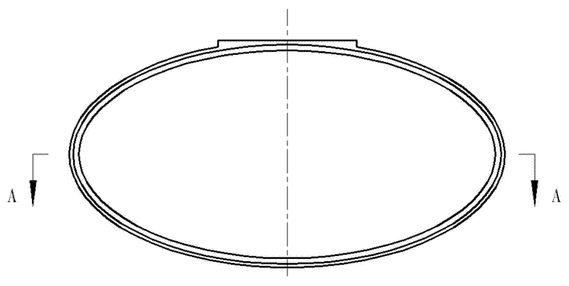
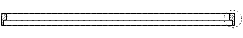
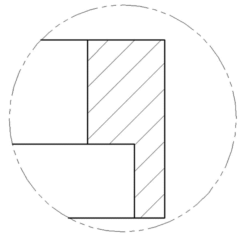
[0024] See attached Figure 5 , a finite element compensation method for deformation of CNC machining parts, the steps are as follows: (1) use modeling software to save the part as a digital model; (2) convert the digital model to finite element analysis software to establish a finite element model; (3) ) Define the unit, section and material, and complete the unit mesh division; (4) Add loads and constraints according to the working conditions, and calculate the deformation of the part caused by the clamping force; (5) Output the surface or line to be processed The amount of deformation of each node; (6) According to the amount of deformation, use the modeling software to draw the shape of the part after being clamped; (7) Carry ...


PUM


Abstract

The invention relates to a finite element compensation method for the deformation of a numerical control processed part, which comprises the following steps: saving the part as a digital model by using modeling software, converting the digital model to finite element analysis software, establishing a finite element model, defining a unit, a section and a material, completing the division of a unit grid, adding load and constraint according to a working condition, and performing calculation on the deformation of the part, which is caused by a clamping force borne by the part; outputting the deformation of all nodes on a plane or a line which needs to be processed, and drawing out the shape of the part under the clamping force according to the deformation by using the modeling software; according to the shape of the part under the clamping force, performing numerical control programming; and after processing is ended, loosening clamping to return the elasticity of the part to be normal. In the finite element compensation method for the deformation of the numerical control processed part, computer finite element analysis software and computer-aided design/computer-aided manufacturing (CAD/CAM) software are utilized, and a special fixture or special equipment does not need to be designed or manufactured, thereby, the processing cost is saved, the production efficiency is improved, and the processing quality is ensured.

Description

technical field [0001] The invention relates to the field of numerical control machining in mechanical manufacturing, and specifically belongs to a finite element compensation method for deformation of a numerical control machining part. Background technique [0002] In the existing technology, when processing easily deformable workpieces, the clamping force of the machine tool deforms the parts, and after the elastic recovery of the parts, the size and shape will change. If the method of reducing the clamping force is used, the cutting amount can only be reduced, and it cannot be completely Eliminate distortion. There are also special fixtures designed and manufactured to disperse the clamping force or change the direction of the clamping force, so that the deformation of the parts caused by the clamping force can be reduced or eliminated. Ring-shaped workpiece CNC machining fixture device", which uses a ring-mounted fixture to clamp easily deformable workpieces to reduce ...

Claims


Application Information

Patent Timeline
Patent Type & Authority Applications(China)
IPC IPC(8): G05B19/4097
CPCY02P90/02
Inventor 刘镝时
Owner SHANGHAI DIANJI UNIV
Why Eureka
Try Eureka