Ultrasonic vacuum energy-saving cleaning machine

A technology of ultrasonic waves and cleaning machines, applied in cleaning methods and appliances, cleaning methods using liquids, chemical instruments and methods, etc., can solve the problems of affecting the heat treatment quality of the workpiece surface, reducing the cleaning effect of the workpiece surface, and cannot be cleaned, etc., to achieve Cleaning time is shortened, work efficiency is improved, and energy consumption is saved

Inactive Publication Date: 2012-02-22
TLON TECHN FURNACES WUXI
View PDF4 Cites 7 Cited by
  • Summary
  • Abstract
  • Description
  • Claims
  • Application Information

AI Technical Summary

Problems solved by technology

[0002] In the existing vacuum cleaning equipment for heat treatment, after the workpiece soaked in the cleaning solution is vacuumed, the lipid dirt on the surface of the workpiece is peeled off by foaming and stirring the solvent. Due to the influence of the gas pressure, the solvent foams The stirring intensity generated is relatively weak, the cleaning time is long, and the energy consumption is large. The lipid dirt in the surface of the workpiece, blind holes and the narrow gap between the workpiece and the workpiece is not easy to be stripped off, especially the non-dissolving part attached to the surface of the workpiece. Permanent dirt cannot be removed, which greatly reduces the cleaning effect of the workpiece surface and seriously affects the heat treatment quality of the workpiece surface

Method used


Image

  • Ultrasonic vacuum energy-saving cleaning machine
  • Ultrasonic vacuum energy-saving cleaning machine
  • Ultrasonic vacuum energy-saving cleaning machine

Examples


Embodiment Construction

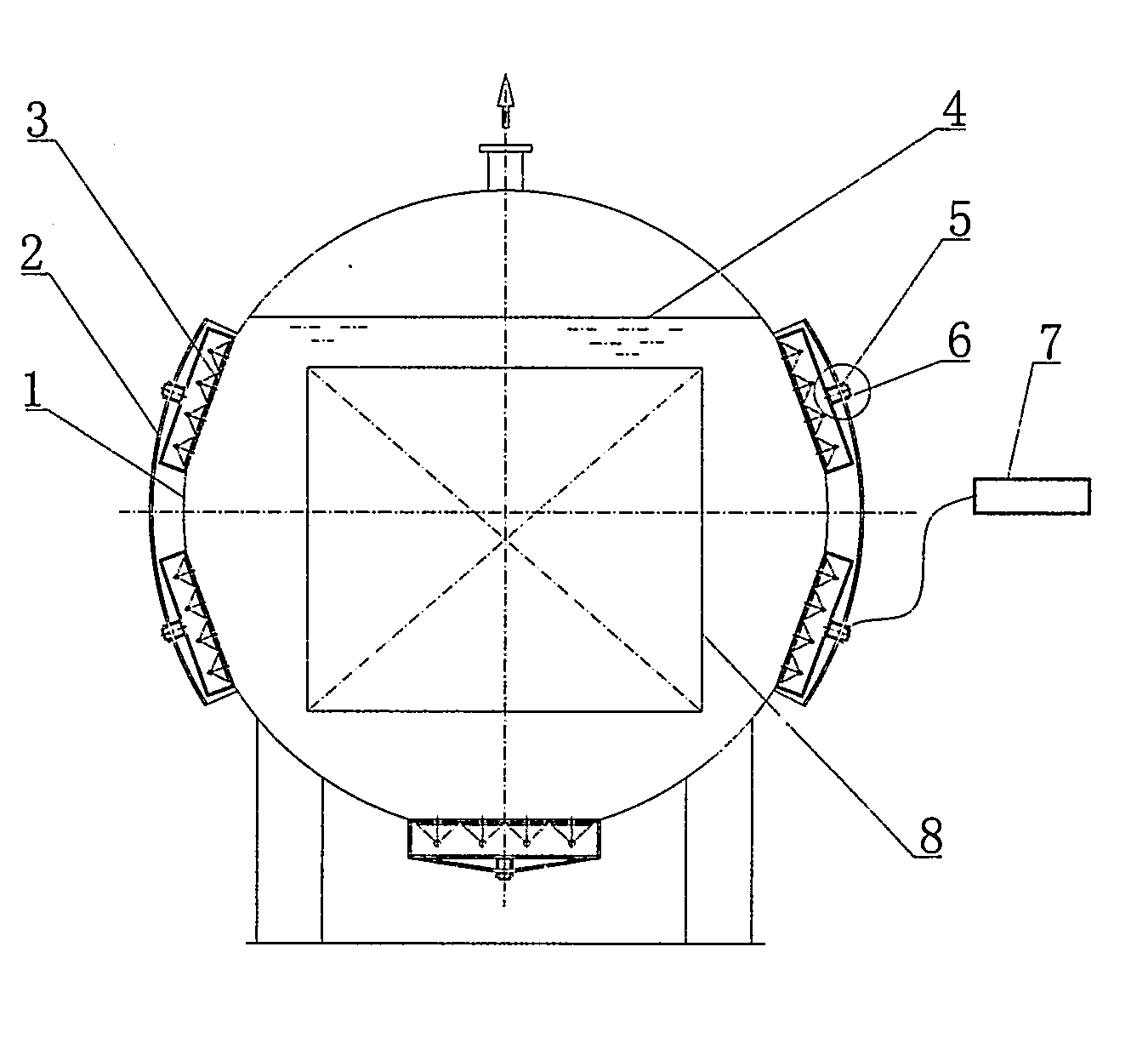
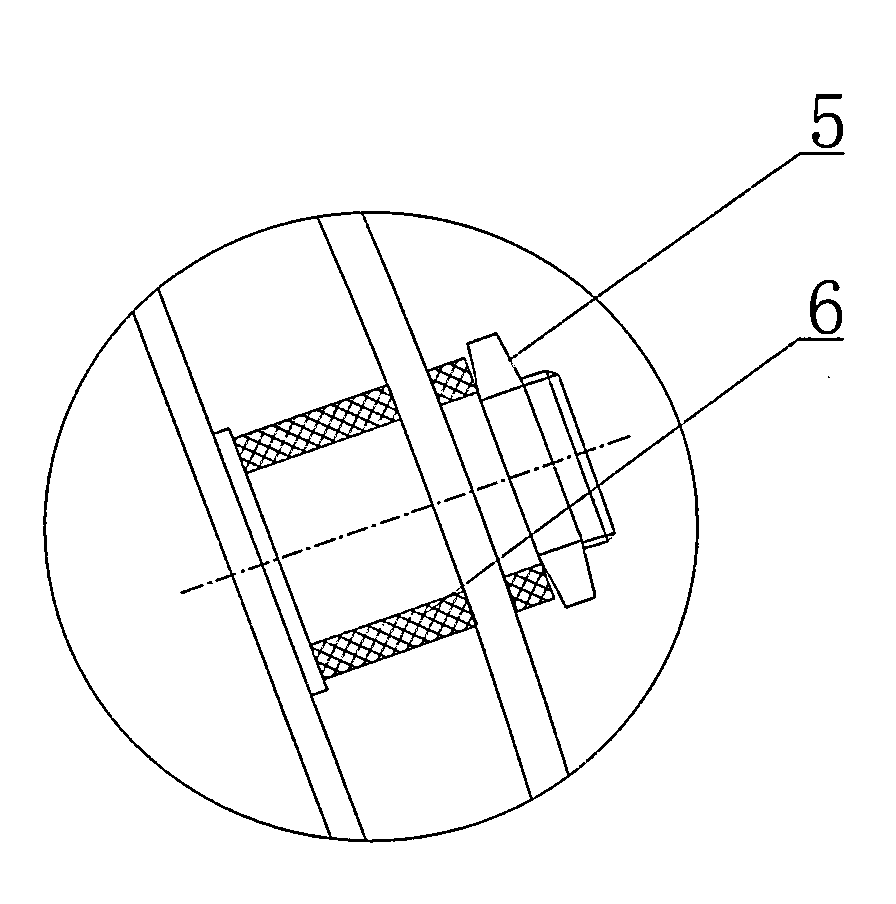
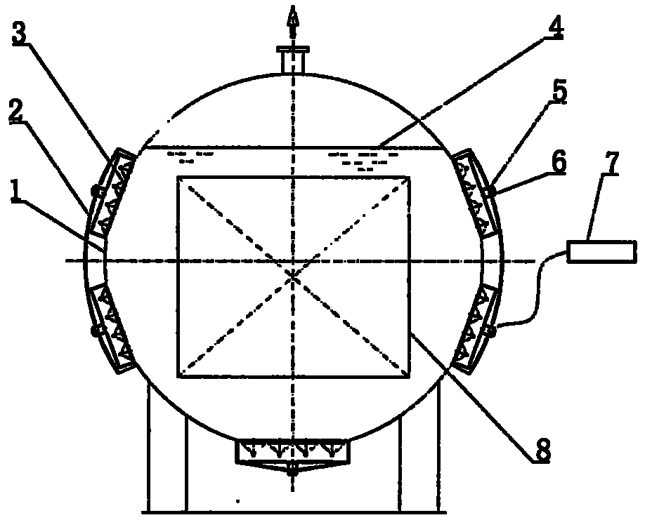
[0009] combine figure 1 , figure 2 , a plurality of grooves 2 are arranged on the periphery of the vacuum chamber 1, and the ultrasonic vibrating plate 3 is evenly installed in the inner groove 2 below the liquid level of the water-based cleaning solvent 4, and the connection with the locking nut 5 and the sealing gasket 6 is realized. The connection and sealing of the vacuum chamber 1, the control line of the ultrasonic generator 7 is connected with the ultrasonic vibration plate 3, the ultrasonic generator 7 works to generate high-frequency signals and transmits them to the ultrasonic vibration plate 3, and the ultrasonic vibration plate 3 converts the high-frequency signals into ultrasonic waves , the ultrasonic waves generate a large number of high-pressure bubbles in the water-based cleaning solvent 4, and move toward the workpiece direction. After the high-pressure bubbles touch the surface of the workpiece 8, they are continuously washed away to peel off the dirt. In ...


PUM


Abstract

The invention discloses an ultrasonic vacuum energy-saving cleaning machine which is used for heat treatment continuous production and belongs to the field of heat treatment cleaning equipment, and particularly discloses a novel ultrasonic vacuum energy-saving cleaning machine which combines an ultrasonic technology and a vacuum solvent cleaning technology. The novel ultrasonic vacuum energy-saving cleaning machine is characterized in that: a plurality of grooves are formed below the liquid level of a vacuum chamber; ultrasonic vibration plates are arranged in the grooves and are connected with ultrasonic generators to ensure that high-frequency signals which are generated by the ultrasonic generators are transmitted to the ultrasonic vibration plates; and the ultrasonic vibration plates convert the high-frequency signals into continuous ultrasonic waves which continuously impact the surface of an object to ensure that dirt which is difficult to dissolve on the surface of the object, and in blind holes and gaps can be peeled off quickly. In the machine, the double combined cleaning functions of ultrasonic waves and vacuum solvent cleaning can be fully exerted, so soluble dirt and insoluble dirt can be cleaned completely; meanwhile, working efficiency is improved, cleaning time is shortened by one third, water consumption is reduced by 30 percent, power consumption is saved by 25 percent, and aims of saving energy and reducing consumption, improving heat treatment quality and reducing production cost are fulfilled.

Description

technical field [0001] The patent of the present invention belongs to the field of heat treatment and cleaning equipment, and specifically refers to a low-cost, low-consumption heat treatment workpiece dirt cleaning and stripping technology. Background technique [0002] In the existing vacuum cleaning equipment for heat treatment, after the workpiece soaked in the cleaning solution is vacuumed, the lipid dirt on the surface of the workpiece is peeled off by solvent foaming and stirring. Due to the influence of gas pressure, the solvent foams The stirring intensity generated is relatively weak, the cleaning time is long, and the energy consumption is large. The lipid dirt in the workpiece surface, blind hole and the narrow gap between the workpiece and the workpiece is not easy to be stripped off, especially the non-dissolving part attached to the workpiece surface. The permanent dirt cannot be removed, which greatly reduces the cleaning effect of the workpiece surface and s...

Claims


Application Information

Patent Timeline
Patent Type & Authority Applications(China)
IPC IPC(8): B08B7/04B08B3/12B08B3/08
Inventor 湛宪宪方华浦晓东林新培毛润辉吴靖
Owner TLON TECHN FURNACES WUXI
Why Eureka
Try Eureka