
Machine tool and method for machining spiral bevel gear

A technology of spiral bevel gears and machine tools, which is applied in the direction of gear cutting machines, components with teeth, metal processing equipment, etc., can solve the problems that affect the production efficiency of gear processing and the automatic loading and unloading of machine tools, etc. Easy and convenient chip removal

Active Publication Date: 2012-02-22
CHANGSHA HALIANG KAISHUAI PRECISION MASCH CO LTD
View PDF6 Cites 15 Cited by
  • Summary
  • Abstract
  • Description
  • Claims
  • Application Information

AI Technical Summary

Problems solved by technology

However, these machine tools cannot automatically load and unload materials, which affects the production efficiency of gear processing

Method used


Image

  • Machine tool and method for machining spiral bevel gear
  • Machine tool and method for machining spiral bevel gear
  • Machine tool and method for machining spiral bevel gear

Examples


Embodiment Construction

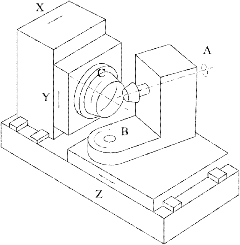
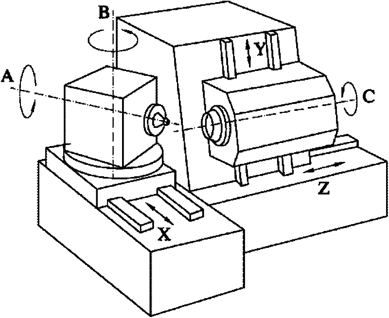
[0057] Such as Figure 4-Figure 6 As shown, a machine tool for processing spiral bevel gears has a bed 1, and the right and left sides and the rear side of the bed 1 are respectively provided with a right wallboard 2, a left wallboard 12 and a rear wallboard 21, and the right wallboard 2 and The left wall panel 12 is parallel, and the upper part of the right wall panel 2 and the left wall panel 12 is respectively provided with an X-axis guide rail 3 parallel to the ground, and the X-axis guide rail 3 is equipped with an X-axis that can move forward and backward along the X-axis guide rail 3 under power drive. The slide table 4; the front side and the upper side of the X-axis slide table 4 are respectively provided with a Y-axis guide rail 5 parallel to the ground and perpendicular to the X-axis guide rail 3. The Y-axis slide table 6 that moves left and right; the front side of the Y-axis slide table 6 is equipped with a Z-axis chute 7 perpendicular to the ground, and the Z-axi...


PUM


Abstract

The invention relates to numerical-control mechanical processing equipment and methods, in particular to a machine tool and a method for machining a spiral bevel gear. The machine tool is provided with a conveyer belt for automatically loading / unloading and a manipulator for loading / unloading the gear, thus, the full automation for machining the gear is realized. The machine tool has a simple structure and a small floor space, can be used for wet-cutting the spiral bevel gear, and can also be used for dry-cutting the spiral bevel gear; the machine tool can be used as a teeth-milling machine of the spiral bevel gear, and can also be used as a teeth-grinding machine of the spiral bevel gear; and the machine tool not only can carry out precision detection on machined gears, but also is provided with an automatic loading / unloading device.

Description

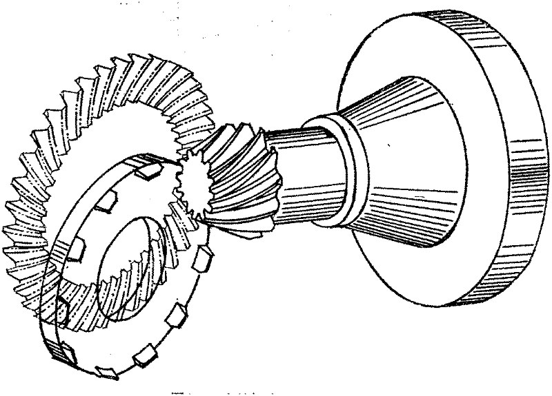
technical field [0001] The invention relates to numerical control machining equipment and methods, in particular to machine tools and methods for processing spiral bevel gears. Background technique [0002] The principle of spiral bevel gear processing machine tool is as follows: figure 1 As shown, the cradle is used to represent the shape wheel, and the cutting surface formed by the cutting edge movement of the tool (cutter disc or grinding wheel) represents a tooth on the shape wheel. During processing, the shape wheel and the gear rotate around their respective axes for meshing motion , the tool can process a gear tooth on the wheel blank. The shape of the tooth surface of the spiral bevel gear depends on the relative position of the cutter head and the workpiece at any time. Assuming that the workpiece does not move, the position of the cutter head in space is determined by the position of the center of the cutter head (three coordinates) and the direction of the axis o...

Claims


Application Information

Patent Timeline
Patent Type & Authority Applications(China)
IPC IPC(8): B23F9/00B23F23/00
Inventor 曾亦愚贾立冬曾韬
Owner CHANGSHA HALIANG KAISHUAI PRECISION MASCH CO LTD
Learn More