Automobile air conditioning system

An automotive air-conditioning system and air-conditioning technology, applied in air-conditioning systems, vehicle components, air handling equipment, etc., can solve problems such as air quality deterioration, acceleration difficulties, and line aging, and achieve fuel consumption savings, significant energy saving and environmental protection, and reduce renovation costs Effect

Inactive Publication Date: 2012-02-22
齐峰
View PDF6 Cites 8 Cited by
  • Summary
  • Abstract
  • Description
  • Claims
  • Application Information

AI Technical Summary

Problems solved by technology

Even if the air conditioner of the new car works well, after two or three years, due to the high mileage of the bus every year, there are common problems such as aging lines, damaged air conditioners, and insufficient horsepower after the air conditioner is turned on.
In addition, since the unit of the top-mounted air conditioner is exposed to the outside, the long-term wind and sun will easily cause the aging of the air-conditioning components, and also affect the appearance of the vehicle
[0005] Therefore, the current design of the air-conditioning system for urban cars is not ideal, and there are many problems that need to be solved urgently: such as poor cooling effect, slow cooling, flameout when starting, difficult acceleration, insufficient power when climbing, and fuel consumption when the air conditioner is running. Big and so on
[0007] (4) At the turn of spring and summer, many bus companies did not regularly clean and disinfect the carriages, and did not clean and maintain the air-conditioning system
As a result, the air in the compartment is dirty and the air quality in the compartment is poor, which is conducive to the growth of bacteria
When the temperature outside the car is high and the humidity is low, the air condition

Method used


Image

  • Automobile air conditioning system
  • Automobile air conditioning system
  • Automobile air conditioning system

Examples


Example Embodiment

[0037] The content of the present invention will be described in detail below in conjunction with the drawings and specific implementations of the specification:

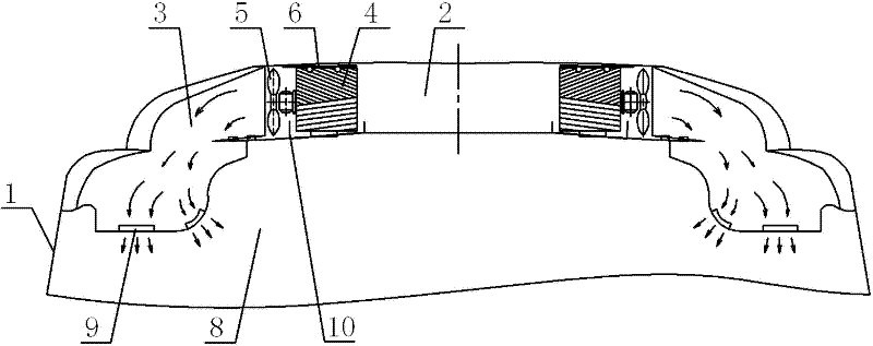
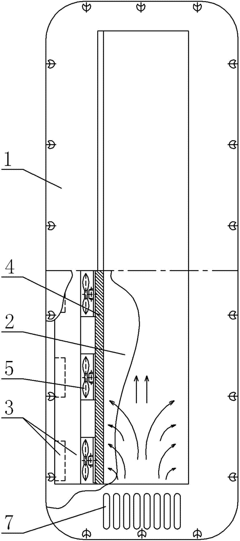
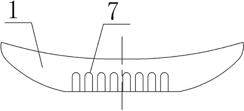
[0038] Such as Figure 1-Figure 6 Shown is a schematic structural diagram of an embodiment of an automobile air conditioning system provided by the present invention, and is characterized in that: the automobile air conditioning system includes an air inlet channel 2 arranged on the top of the vehicle body 1 and extending along the front and rear direction of the vehicle body 1 The air outlet channels 3 on the left and right sides of the air inlet channel 2, the wet curtain 4 arranged between the air inlet channel 2 and the air outlet channel 3, and the air outlet channel 3 at the entrance to pass the air from the air inlet channel 2 The fan 5 drawn to the air outlet channel 3, a water distribution pipe 6 arranged on the top or side of the wet curtain 4 to distribute water to the wet curtain 4, and a water supply devic...


PUM


Abstract

The technical scheme of the invention relates to an automobile air conditioning system. The automobile air conditioning system is characterized by comprising an air inlet channel which is arranged on the top of an automobile body and extends along a front-and-after direction of the automobile body, air outlet channels which are arranged on the left side and the right side of the air inlet channel respectively, wet curtains blocked between the air inlet channel and the air outlet channels, fans which are arranged at the entrances of the air outlet channels and used for extracting air from the air inlet channel to the air outlet channels, water distribution pipelines which are arranged on the top or lateral parts of the wet curtains and used for distributing water on the wet curtains, and a water supply device connected with the water distribution pipelines to supply water, wherein an air inlet for communicating the air inlet channel with air outside the automobile body is formed on the top of the automobile body; and air outlets for communicating the air outlet channels with air in a carriage are formed on the top or the lateral parts of the carriage. The automobile air conditioning system realizes temperature reduction by adopting a water evaporation effect theory and using a physical method; and the automobile air conditioning system is a complete coolant-free, heat pollution-free, energy-saving and environment-friendly automobile air conditioner.

Description

technical field [0001] The invention relates to an automobile air-conditioning system, which is applicable to automobiles such as buses and passenger cars. Background technique [0002] The air-conditioning systems of urban public transport vehicles commonly used at present have the following characteristics: [0003] (1) Although many urban traffic control departments have stipulated whether the bus is air-conditioned or not, it is subject to the weather forecast of the day. As long as the maximum temperature reaches 28°C, the bus must be air-conditioned, but many buses consider energy consumption. It is stipulated that the air conditioner should be turned on from June 1st to October 30th every year. When the air conditioning facility is not in use, only the vehicle ventilation facility should be turned on. In this way, whether to turn on the air conditioner cannot be adjusted according to the actual temperature. Even if the weather is very hot in spring and autumn, the ai...

Claims


Application Information

Patent Timeline
IPC IPC(8): B60H1/32B60H3/02B60H1/30F24F5/00
CPCY02T10/88
Inventor 齐峰
Owner 齐峰
Why Eureka
Try Eureka