Power apparatus for aircraft

A power device and aircraft technology, which is applied in the direction of driving multiple propellers, aircraft parts, transportation and packaging, etc., can solve the problems of low power factor, poor flight performance, and reduced reliability of axial fans, and achieve high performance Excellent, high power load, simple construction effect

Inactive Publication Date: 2012-02-22
陈志灵
View PDF6 Cites 3 Cited by
  • Summary
  • Abstract
  • Description
  • Claims
  • Application Information

AI Technical Summary

Problems solved by technology

[0002] Current aircraft, especially vertical take-off and landing aircraft such as helicopters, use the lift and thrust produced by the axial fan, that is, the rotor to make it rise and fly forward, but the axial fan has a low power factor, which only reaches 40% of its effective power Left and right, the power load is low, the flight performance is poor, and the rotor diameter is too large. If the rotor speed is too high, a vacuum will be generated at the wing tip, and the air separation will make its efficiency drop sharply. It is used as a helicopter rotor. In order to prevent it from flying forward Tilting requires a complex mechanism to control the movement of the rotor, so its structure becomes complicated, the cost is high, and the reliability is reduced

Method used


Image

  • Power apparatus for aircraft
  • Power apparatus for aircraft
  • Power apparatus for aircraft

Examples


Embodiment 1

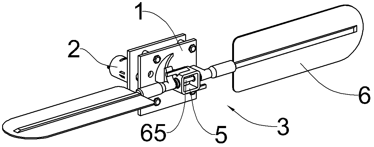
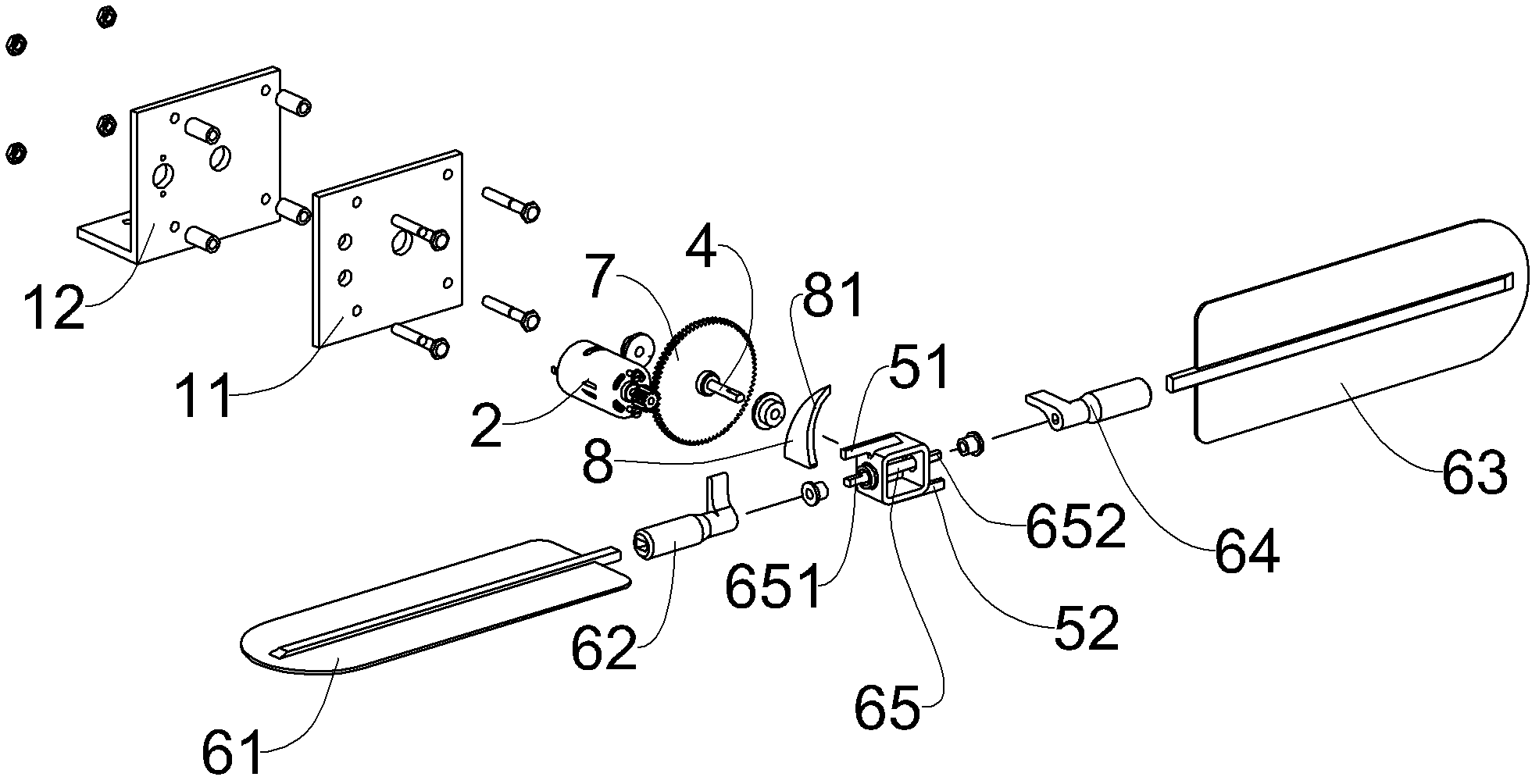
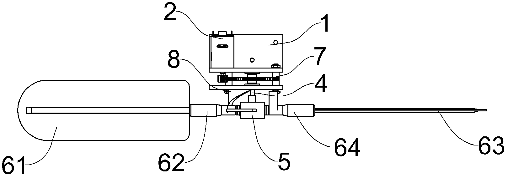
[0032] Figure 1 to Figure 4 A power device for an aircraft is shown, comprising a base 1, a motor 2 as a driving source, and a propeller 3 driven by the motor 2, and the propeller 3 includes a propeller shaft 4, a propeller hub 5 and a propeller The blade assembly 6, the motor 2 is connected with the propeller shaft 4 through the transmission gear set 7 to drive its rotation, the propeller shaft 4 and the blade assembly 6 are connected through the propeller hub 5, when the propeller shaft 4 rotates, its Drive the propeller hub 5 and the propeller assembly 6 to rotate around the axis of the propeller shaft 4 together. The base 1 is composed of a front base plate 11 and a rear base plate 12. The motor 2 is mounted on the rear side of the rear base plate 12. The transmission gear set 7 is located between the front base plate 11 and the rear base plate 12. The propeller shaft 4 passes through the front base plate 11.

[0033] The paddle assembly 6 includes a first blade 61, a fi...

Embodiment 2

[0038] Figure 10 and Figure 11 The power unit shown for the aircraft also includes a base 1, a motor 2 as a driving source, and a propeller 13 driven by the motor 2 to rotate. The propeller 13 includes a propeller shaft 14, a hub 15 and a "Four groups of paddle assemblies 161, 162, 163, 164 distributed in the shape of a font, the motor 2 is connected with the propeller shaft 14 through the transmission gear set 7 to drive its rotation, the propeller shaft 14 and the four groups of paddle assemblies 161, 162, 163 , 164 are connected by the propeller hub 15 , when the propeller shaft 14 rotates, it drives the propeller hub 15 and four sets of blade assemblies 161 , 162 , 163 , 164 to rotate around the axis of the propeller shaft 14 together. The base 1 is composed of a front base plate 11 and a rear base plate 12. The motor 2 is mounted on the rear side of the rear base plate 12. The transmission gear set 7 is located between the front base plate 11 and the rear base plate 12...

Embodiment 3

[0045] Such as Figure 14 to Figure 19 As shown, the power unit of this embodiment also includes a base 1, a motor 2, and a propeller 23 driven by the motor 2, which are similar to those shown in the first embodiment. In addition, this embodiment is also A volute 20 is added on the basis of the power device shown in Embodiment 1. The bottom of the volute 20 has an air outlet 201 , and the upper part has an air inlet 202 . The propeller 23 is arranged inside the volute 20 . When the propeller 23 rotates in the volute 20, an airflow is generated, and the volute 20 plays the role of guiding the airflow and concentrating it to be ejected from the air injection port 201. When the air injection port 201 sprays downward, a lift is generated, and when the air injection port 201 sprays air backward produce forward thrust.


PUM


Abstract

The present invention provides a power apparatus for an aircraft. The apparatus comprises a base, a drive source and a rotation propeller, wherein the drive source drives the rotation propeller to rotate. The rotation propeller comprises a rotation propeller shaft and a propeller blade assembly. The rotation propeller shaft forms a rotatable connection with the drive source. The propeller blade assembly is provided with a propeller blade shaft, wherein the propeller blade shaft is perpendicular to the rotation propeller shaft, and can rotate around the axial line of the propeller blade shaft. The base is provided with a cam part, and a guidance part with a preset shape is formed on the cam part. The propeller blade assembly is provided with a conduction part and a rotation angle spacing part, wherein the conduction part contacts the guidance part to drive the propeller blade assembly to rotate around the propeller blade shaft, the rotation angle spacing part limits the rotation angle of the propeller blade assembly around the propeller blade shaft. According to the present invention, the problems of requirements of large amount of continuous and stable air working medium with a certain dynamic pressure energy during the vertical aircraft taking off and landing process are solved; the power apparatus provided by the present invention has characteristics of simple structure, large power load, high efficiency and convenient and flexible operation.

Description

technical field [0001] The invention relates to a power plant for an aircraft. Background technique [0002] Current aircraft, especially vertical take-off and landing aircraft such as helicopters, use the lift and thrust produced by the axial fan, that is, the rotor to make it rise and fly forward, but the axial fan has a low power factor, which only reaches 40% of its effective power Left and right, the power load is low, the flight performance is poor, and the rotor diameter is too large. If the rotor speed is too high, a vacuum will be generated at the wing tip, and the air separation will make its efficiency drop sharply. It is used as a helicopter rotor. In order to prevent it from flying forward Tipping requires a complex mechanism for controlling the rotor motion, so its structure becomes complicated, the cost is high, and the reliability is reduced. Contents of the invention [0003] The technical problem to be solved by the present invention is to provide a ...

Claims


Application Information

Patent Timeline
Patent Type & Authority Applications(China)
IPC IPC(8): B64C11/10B64D35/06
Inventor 陈志灵
Owner 陈志灵
Why Eureka
Try Eureka