Stirred tank reactor

A stirred tank and reactor technology, which is applied in the field of stirred tank reactors for olefin slurry polymerization, can solve the problems of shortening the cleaning cycle of the heat exchanger, increasing the scaling of the heat exchanger, decreasing the heat exchange capacity, etc. The effect of reducing residence time, slurry entrainment, and reducing operating costs

Inactive Publication Date: 2012-02-22
ZHEJIANG UNIV
1 Cites 35 Cited by

AI-Extracted Technical Summary

Problems solved by technology

A large amount of slurry entrainment will cause more and more solids to enter the tank top heat exchanger, resulting in increased fouling of the heat exchanger...

Method used

The third layer of turbine 11 is an upflow type axial flow turbine, and the distance from the blade outer edge of the third layer of turbine 11 to the hub center of the third layer of turbine 11 is greater than that of the disk outer edge of the second layer of turbine 10 to the second The distance between the hub centers of the layer turbine 10 is small. Furthermore, the distance from the outer edge of the blades of the third turbine 11 to the center of the hub of the third turbine 11 is 0.5-0.9 from the outer edge of the disc of the second turbine 10 to the center of the hub of the second turbine 10 . Such an arrangement is conducive to the formation of radial circulation in the middle area of ​​the stirred tank.
[0056] The baffle 14 shown in FIG. 1 is a straight baffle. There are 2 to 8 straight baffles, preferably 4 or 8, and the baffles 14 are installed equidistantly from the wall on the inner wall of the stirred tank body 1 to eliminate dead spots for solid deposition and enhance the mixing effect in the stirred tank. The gas distribution device 15 shown in FIG. 1 consists of an air inlet pipe extending through the top of the stirred tank body 1 to the bottom of the stirred tank body 1 and ...

Abstract

The invention discloses a stirred tank reactor and aims at improving a stirring turbine in the stirred tank reactor by using a four-layer combination stirring turbine. The stirring turbine comprises a first layer turbine, a second layer turbine, a third layer turbine and a fourth layer turbine which are arranged from the middle to the bottom of a stirring shaft sequentially. The first layer turbine is an upward axial flow turbine, the second layer turbine is a disk type turbine, the third layer turbine is an upward axial flow turbine, and the fourth layer turbine is a radial flow turbine. Radial circulation close to a liquid level, radial circulation close to a middle area of a stirred tank and radial circulation in a bottom area of the stirred tank are formed, so that circulation quantity inside the stirred tank is big and mixing time is short. Poor mixing area does not exist, and solid containing rate and gas containing rate are evenly distributed. A mass transfer condition of air and liquid is good, and single transfer efficiency is high. Entrainment quantity of sizing is greatly reduced, fouling of a heat exchanger is reduced, and service life is long. Operation cost is lowered, and production cost is saved.

Application Domain

Technology Topic

Image

  • Stirred tank reactor
  • Stirred tank reactor
  • Stirred tank reactor

Examples

  • Experimental program(1)
  • Comparison scheme(1)
  • Effect test(1)

Example Embodiment

[0062] Example 1
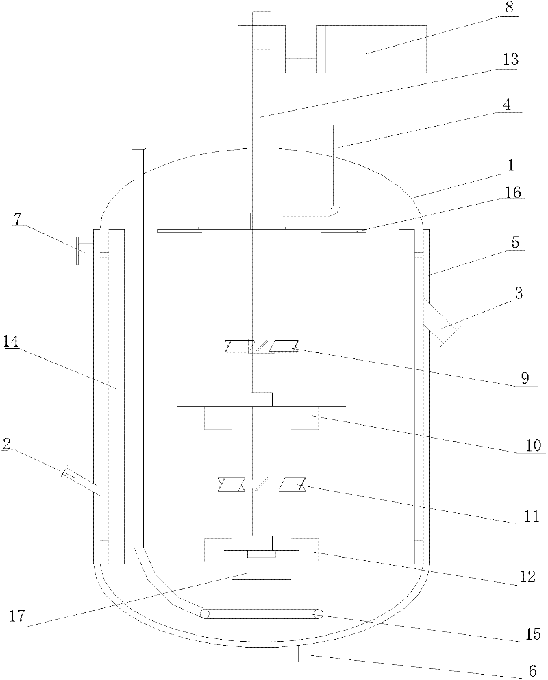
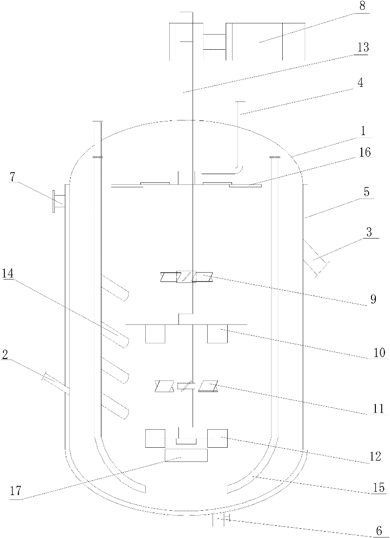
[0063]Embodiment 1 adopts a specific structure of the stirred tank reactor of the present invention, and there are 8 air inlet pipes, wherein, half of the air inlet pipes run through the top of the stirred tank body 1 and extend to the bottom of the stirred tank body 1, and the other half of the air inlet pipes are at the bottom of the stirred tank body 1. Inside the stirred tank body 1, it extends from the end close to the top to the bottom. The baffle 14 is a finger-shaped baffle, and 4 finger-shaped baffles are equidistantly installed on one intake pipe (1# finger-shaped baffle means the first finger-shaped baffle from the top of the stirring tank to the bottom of the stirring tank) 1# turbine means the first layer of turbines from the top of the stirred tank to the bottom of the stirred tank, and so on, the same below), 4 of the 8 inlet pipes are provided with finger-shaped baffles, a total of 16 finger-shaped baffles shaped baffle.
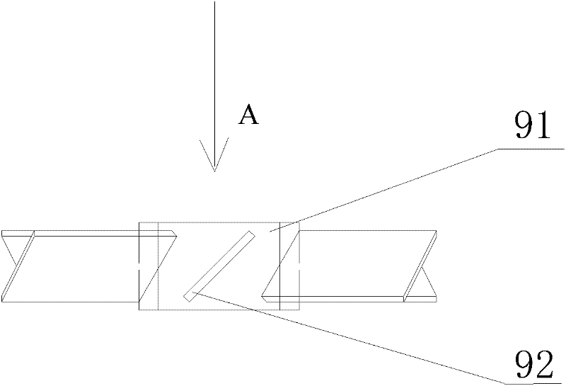
[0064] The first layer of turbine 9 adopts such as image 3 and Figure 4 As shown in the pitched-blade turbine, the second-stage turbine 10 adopts such as Figure 5 and Image 6 As shown in the disk turbine, the third layer of turbine 11 adopts such as Figure 7 and Figure 8 As shown in the inclined-blade disc turbine, the fourth-stage turbine 12 adopts such as Figure 9 and Figure 10 A straight-blade disk turbine is shown. The first layer of turbines 9, the second layer of turbines 10, the third layer of turbines 11 and the fourth layer of turbines 12 adopt the following specific dimensions, and the specific dimensions are shown in Table 1. The diameter (dT) of the ring-shaped guide tube 17 below the fourth-layer turbine 12 is 184 mm, the height (h) is 48 mm, and the disc distance (Δh) from the top of the ring-shaped guide tube 17 to the fourth-layer turbine 12 is 42 mm.
[0065] Table 1
[0066]
[0067] The labeling of other specific dimensions of the stirred tank reactor of the present invention is as Figure 11 Its specific dimensions are shown in Table 2.
[0068] Table 2
[0069]

PUM

no PUM

Description & Claims & Application Information

We can also present the details of the Description, Claims and Application information to help users get a comprehensive understanding of the technical details of the patent, such as background art, summary of invention, brief description of drawings, description of embodiments, and other original content. On the other hand, users can also determine the specific scope of protection of the technology through the list of claims; as well as understand the changes in the life cycle of the technology with the presentation of the patent timeline. Login to view more.

Similar technology patents

Air purification device based on Internet of Things

InactiveCN110920356ALarge circulationImprove humidification efficiencyAir-treating devicesProcess engineeringInternet of Things
Owner:MINJIANG UNIV

Compressor rotor and compressor containing same

Owner:ZHUHAI GREE REFRIGERATION TECH CENT OF ENERGY SAVING & ENVIRONMENTAL PROTECTION

LED counter lamp convenient to install

InactiveCN111649253ALarge circulationPlay the role of compensating support forceLighting applicationsMechanical apparatusFixed frameComputer hardware
Owner:徐州诚凯知识产权服务有限公司

Classification and recommendation of technical efficacy words

  • Short mixing time
  • Large circulation

Process for the manufacture of (poly-)isocyanates in the gas phase

ActiveUS6974880B2High yieldShort mixing timeIsocyanic acid derivatives preparationLiquid-gas reaction as foam/aerosol/bubblesDiamineIsocyanate
Owner:COVESTRO DEUTSCHLAND AG

Sand mixing and stirring cage of precoated sand mixing machine

InactiveCN104646618AShort mixing timeReduce lossesMould handling/dressing devicesEngineeringMixing tank
Owner:WUXI KANGHUI MACHINE BUILDING

Ticket check and payment system and method for urban rail transit financial IC cards

PendingCN107093074ALarge circulationWide coverageTicket-issuing apparatusCredit schemesOperating systemReading card
Owner:GUANGZHOU METRO DESIGN & RES INST

Sorting method of low-grade black and white tungsten fine clay

InactiveCN110918247ALarge circulationImprove concentrate gradeWet separationOre concentrateProcess engineering
Owner:宁化行洛坑钨矿有限公司

Novel bacterium-insulation and dust-tight mask

InactiveCN103704904AIncrease the air filtration areaLarge circulationProtective garmentActivated carbonMetallic materials
Owner:TIANJIN HONGCHENDAO FASHION

Trapezoidal flow electrodeposition apparatus

InactiveCN104775132ALarge circulationReduce concentration polarizationPhotography auxillary processesElectrolysis componentsEngineeringLiquid storage tank
Owner:张家港联合铜业有限公司
Why Eureka
Try Eureka