Engineering structure for improving water and sediment conditions of lock chamber of lock multi-section dispersive water conveyance system

A technology of decentralized water delivery and engineering structure, applied in ship locks, ship lifting devices, river regulation, etc., can solve problems such as reducing the minimum navigable water depth of lock chambers, increasing maintenance workload, and affecting ship navigation, etc., to reduce operation and maintenance Cost, convenient construction and maintenance, and the effect of saving operation and maintenance costs

Inactive Publication Date: 2012-02-22
NANJING HYDRAULIC RES INST
View PDF5 Cites 4 Cited by
  • Summary
  • Abstract
  • Description
  • Claims
  • Application Information

AI Technical Summary

Problems solved by technology

The sediment deposition in the lock chamber is mainly concentrated in the non-water outlet area, namely the upper and lower lock heads of the ship lock, the first and second diversion ports (the diversion port is between the two water outlet sections), and the maximum sediment deposition thickness up to about 3m, thus reducing the minimum navigable water depth of the lock chamber, affecting the navigation of ships, and also increasing the maintenance workload and prolonging the maintenance time
[0005] Therefore, how to improve the water flow conditions and sediment deposition in the sluice chamber of the multi-section decentralized water delivery system has become a problem of great concern to construction, design and scientific research personnel, but there are few successful cases in this regard at home and abroad for reference

Method used


Image

  • Engineering structure for improving water and sediment conditions of lock chamber of lock multi-section dispersive water conveyance system
  • Engineering structure for improving water and sediment conditions of lock chamber of lock multi-section dispersive water conveyance system
  • Engineering structure for improving water and sediment conditions of lock chamber of lock multi-section dispersive water conveyance system

Examples


Embodiment 1

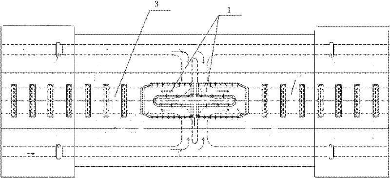
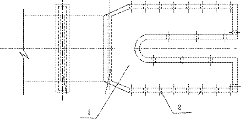
[0019] This embodiment is an engineering structure for improving the water and sand conditions in the lock chamber of the multi-section dispersed water delivery system of the ship lock, such as figure 1 As shown, that is, an auxiliary water outlet corridor 1 is added on the side of the non-water outlet area near the first and last two water outlet branch holes of each branch corridor 3 in each water outlet section. In this embodiment, the ship lock adopts a water conveyance system type with a long corridor on the lock wall, a horizontal diversion in the center of the lock chamber, and water outlets from two sections of the longitudinal long corridor at the bottom of the lock chamber. A U-shaped auxiliary water outlet corridor 1 is respectively set above the water outlet holes on the top. The minimum submerged water depth at the top of the auxiliary water outlet corridor is not less than the threshold water depth of the ship lock; there are several water outlet square holes 2 on...


PUM


Abstract

The invention discloses an engineering structure for improving water and sediment conditions of a lock chamber of a lock multi-section dispersive water conveyance system, which comprises a branch galleries and lock chamber water outlet holes arranged in the branch galleries. The end-to-end joint of each two adjacent branch galleries is respectively provided with an auxiliary water outlet gallery. Each auxiliary water outlet gallery is of a U shape or a rectangular shape. The minimum inundated depth at the top of each gallery is not less than the sill depth of a lock. The side walls of the auxiliary water outlet galleries are provided with a plurality of water outlet holes. Due to the adoption of the engineering structure, the uniformity of effluent in the lock chamber is effectively improved and the sediment deposition can also be prevented. Moreover, the engineering structure has simple structure and is convenient to construct, the operation and maintenance cost is obviously saved, and the engineering structure has good application prospect.

Description

technical field [0001] The invention relates to an engineering structure capable of improving the water flow conditions and sediment deposition conditions in the lock chamber of the multi-section dispersed water delivery system of the ship lock on a sandy navigable river, in particular to an engineering structure for improving the water flow in the lock chamber of the multi-section dispersed water delivery system of the ship lock. Engineered structures for sandy conditions. Background technique [0002] A ship lock is a ship-passing structure that overcomes the concentrated water level difference formed by the dam (or natural) on the river. It is composed of upper and lower lock heads, gates, and lock chambers. The water delivery system is the key facility to complete the filling and discharging process of the lock chamber so that the ship can overcome the concentrated water level difference and achieve the purpose of passing the dam. According to the requirements of differ...

Claims


Application Information

Patent Timeline
Patent Type & Authority Applications(China)
IPC IPC(8): E02B3/02E02C1/06
CPCY02A10/30
Inventor 胡亚安黄岳宣国祥李云李君李中华
Owner NANJING HYDRAULIC RES INST
Why Eureka
Try Eureka