
Method for bracing foundation pit by using steel box piles

A foundation pit enclosure and steel box technology, applied in excavation, sheet pile walls, foundation structure engineering, etc., can solve the problems of inevitable environmental pollution, difficult construction quality assurance, and large environmental impact, so as to protect the environment, The injection range is easy to control and the construction period is short

Inactive Publication Date: 2012-02-22
CHINA RAILWAY SIYUAN SURVEY & DESIGN GRP
View PDF7 Cites 15 Cited by
  • Summary
  • Abstract
  • Description
  • Claims
  • Application Information

AI Technical Summary

Problems solved by technology

[0003] For silty soil, peaty soil, saturated water-bearing sand layer, silty clay, and soil-sand interbedded weak strata that are not easy to form holes and troughs, such as: soft soil strata along the Yangtze River Delta, Pearl River Delta and Bohai Bay and other coastal areas. The alluvial terraces along the Yangtze River and the Pearl River and other rivers adopt the existing foundation pit enclosure technology, which has obvious defects: the common disadvantages of underground diaphragm walls and bored piles are high cost, long construction period, and great impact on the environment ; There are certain difficulties in the recovery of section steel of rigid cement jet grouting (SMW) piles, and the construction quality is not easy to guarantee, which inevitably pollutes the environment, and is not suitable for deep foundation pits; steel sheet piles are only suitable for shallow foundation pits

Method used


Image

  • Method for bracing foundation pit by using steel box piles
  • Method for bracing foundation pit by using steel box piles
  • Method for bracing foundation pit by using steel box piles

Examples


Embodiment Construction

[0050] Below in conjunction with accompanying drawing and specific embodiment the present invention is described in further detail:

[0051] The method for using steel box piles to protect foundation pits includes the following steps:

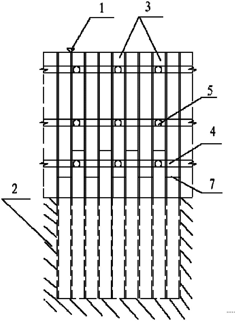
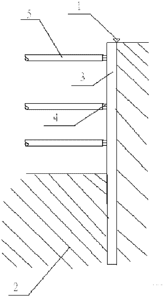
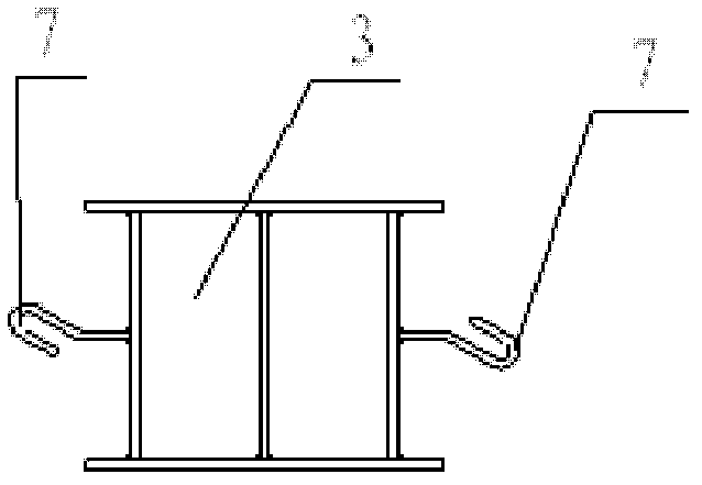
[0052] First, make steel box piles: steel box piles of prefabricated dimensions are welded by section steel or steel plates, such as figure 1 , figure 2 and image 3 As shown, the finished steel box pile box 3 is formed, and the two sides of the steel box pile box 3 are symmetrically provided with connecting members 7 for connecting horizontally adjacent steel box piles. The side of 3 is welded with a hook-shaped plug-in connecting member with a long length, so that the adjacent steel box piles are connected to each other, and the interface of the connecting member of the previous steel box pile becomes the sinking pile of the next steel box pile The guide groove. The hook-shaped socket-type connecting member between the piles is "hinged",...


PUM


Abstract

The invention discloses a method for bracing a foundation pit by using steel box piles. The method comprises the following steps of: (1) making the steel box piles: welding profile steels or steel plates into a steel box pile box, and arranging transverse connecting members among the piles at two sides of the steel box pile box; (2) arranging a ground guiding structure: pouring reinforced concrete to form a foundation pit bracing guiding wall or arranging steel members to form the ground guiding structure; (3) positioning: sequentially positioning a plurality of steel box piles along the guiding structure respectively; (4) sinking the piles: driving the steel box piles into soil; (5) lengthening the piles: when the foundation pit is relatively deep and the prefabricated steel box piles are not long enough, lengthening the steel box piles through pile body lengthening members; and (6) digging and supporting: digging layer by layer, arranging enclosing purlins and erecting supports in the foundation pit of the steel box piles, and completing the construction. The method has the advantages of high construction efficiency, short construction period, reliable pile forming quality, low engineering cost, resource economization and the like, and is particularly suitable for weak strata in which holes and grooves are not easily formed such as silt soil, peat soil, saturated water-containing sand layers, powdery clay, soil sand and the like.

Description

technical field [0001] The invention relates to the technical field of foundation pit enclosure protection for underground engineering in the field of construction, and is particularly suitable for silty soil, peaty soil, saturated water-bearing sand layer, silty clay, and soil-sand interbeds, etc., which are not easy to form holes and grooves. Ground pit protection method. Background technique [0002] There are many open-cut deep foundation pits in underground railways, urban roads and high-rise building projects. Existing retaining structures for foundation pits usually adopt a variety of retaining forms such as underground diaphragm walls, bored piles, driven piles, and rigid cement jet grouting (SMW) piles. [0003] For silty soil, peaty soil, saturated water-bearing sand layer, silty clay, and soil-sand interbedded weak strata that are not easy to form holes and troughs, such as: soft soil strata along the Yangtze River Delta, Pearl River Delta and Bohai Bay and other...

Claims


Application Information

Patent Timeline
IPC IPC(8): E02D17/02E02D5/04E02D5/52
Inventor 周心培周磊
Owner CHINA RAILWAY SIYUAN SURVEY & DESIGN GRP
Learn More