Self-healing optical current transformer
A technology of current transformers and current sensors, applied in inductors, voltage/current isolation, circuits, etc., can solve the problems of poor operation reliability, low measurement accuracy, and poor temperature stability, and achieve high reliability and measurement accuracy. High, good temperature stability effect
- Summary
- Abstract
- Description
- Claims
- Application Information
AI Technical Summary
Problems solved by technology
Method used
Image
Examples
specific Embodiment approach 1
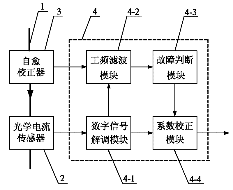
[0011] Specific implementation mode one: combine figure 1 Describe this embodiment, this embodiment is made up of optical current sensor 2, self-healing calibrator 3 and algorithm realization unit 4; Algorithm realization unit 4 is made up of digital signal demodulation module 4-1, power frequency filtering module 4-2 fault judgment module 4-3 and the coefficient correction module 4-4; the optical current sensor 2 and the self-healing corrector 3 are respectively installed on the power transmission bus 1, and the data signal output terminal of the optical current sensor 2 is connected with the digital signal solution in the algorithm realization unit 4 The data signal input end of the modulation module 4-1 is connected, the first signal output end of the digital signal demodulation module 4-1 is connected with the second signal input end of the power frequency filter module 4-2, and the digital signal demodulation module 4-1 The second signal output end of the self-healing cor...
specific Embodiment approach 2
[0012] Specific implementation mode two: combination Figure 8 Describe this embodiment. The difference between this embodiment and the specific embodiment is that the self-healing calibrator 3 is composed of a light-load coil module 3-1, a sampling resistor module 3-2, a high-voltage power supply module 3-3, and a high-voltage side circuit 3- 10 and the low-voltage side circuit 3-11; the high-voltage side circuit 3-10 is composed of an overvoltage protection circuit 3-4, a bias circuit 3-5, a frequency modulation circuit 3-6 and a high-voltage electro-optical conversion circuit 3-7; the low-voltage side The circuit 3-11 is composed of a low-voltage electro-optical conversion circuit 3-8 and a signal demodulation circuit 3-9; the signal input end of the light-load coil module 3-1 is the signal input end of the self-healing calibrator 3, and the light-load coil module 3-1 The signal output terminal of 1 is connected to the signal input terminal of the sampling resistor module 3...
specific Embodiment approach 3
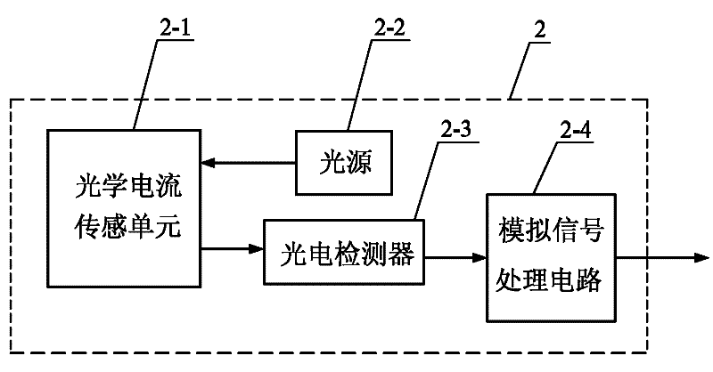
[0013] Specific implementation mode three: combination figure 2 Describe this embodiment, the difference between this embodiment and the specific embodiment is that the optical current sensor 2 is composed of an optical current sensing unit 2-1, a light source 2-2, a photodetector 2-3 and an analog signal processing circuit 2-4 The light emitting end of the light source 2-2 is connected with the light incident end of the optical current sensing unit 2-1, the signal output end of the optical current sensing unit 2-1 is connected with the signal input end of the photodetector 2-3, and the photoelectric The data signal output end of the detector 2-3 is connected with the data signal input end of the analog signal processing circuit 2-4, and the data signal output end of the analog signal processing circuit 2-4 is the data signal output end of the optical current sensor 2. Other compositions and connection methods are the same as those in Embodiment 1.
PUM
 Abstract
Description
Claims
Application Information
 - R&D
- Intellectual Property
- Life Sciences
- Materials
- Tech Scout
- Unparalleled Data Quality
- Higher Quality Content
- 60% Fewer Hallucinations
Browse by: Latest US Patents, China's latest patents, Technical Efficacy Thesaurus, Application Domain, Technology Topic, Popular Technical Reports.
© 2025 PatSnap. All rights reserved.Legal|Privacy policy|Modern Slavery Act Transparency Statement|Sitemap|About US| Contact US: help@patsnap.com


