Intermediate frequency induction heat treatment device for steel tubes, and heat treatment method of the same

A technology of induction heat treatment and steel pipes, applied in heat treatment furnaces, heat treatment equipment, heat treatment process control, etc., to achieve the effects of small grain size, fast heating speed, and uniformity

Inactive Publication Date: 2012-02-29
NORTHEASTERN UNIV LIAONING
View PDF2 Cites 14 Cited by
  • Summary
  • Abstract
  • Description
  • Claims
  • Application Information

AI Technical Summary

Problems solved by technology

Medium frequency induction has been applied in the industrial production of steel pipes, such as Anshan Iron and Steel Co., Ltd. Seamless Steel Pipe Factory, Xining Special Steel, Jiangyin Changjiang Seamless Steel Pipe Factory, etc., but they are only used in heating up, expanding or The simple heating process during pipe bending has not been practically applied to the online continuous heat treatment of finished steel pipes such as cold-drawn seamless steel pipes or welded pipes.

Method used


Image

  • Intermediate frequency induction heat treatment device for steel tubes, and heat treatment method of the same
  • Intermediate frequency induction heat treatment device for steel tubes, and heat treatment method of the same
  • Intermediate frequency induction heat treatment device for steel tubes, and heat treatment method of the same

Examples


Embodiment 1

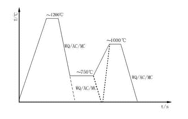
[0042] Start the motor to rotate the double-cone roller, and transport the steel pipe to the preheating furnace at a running speed of 0.5cm / s to preheat to 200°C;

[0043] Then the steel pipe enters the heating furnace and is heated to 750°C, and the temperature is measured by a portable infrared thermometer. By controlling the output frequency of the intermediate frequency induction power supply to 18kHz, the temperature error of the steel pipe in the furnace is within the range of ±10°C;

[0044] After that, the steel pipe enters the cooling box and is cooled to 20°C;

[0045] The cooled steel pipe enters the tempering furnace and is kept at 200°C;

[0046] Finally, the steel pipe enters the cooling box for water cooling.

Embodiment 2

[0048] Start the motor to rotate the double-cone roller, and send the steel pipe to the preheating furnace at a running speed of 4cm / s to preheat to 400°C;

[0049] Then the steel pipe enters the heating furnace and is heated to 1200°C, using a portable infrared thermometer to measure the temperature, and controlling the output frequency of the intermediate frequency induction power supply to 30kHz, so that the temperature error of the steel pipe in the furnace is within the range of ±10°C;

[0050] The steel pipe enters the cooling box and is air-cooled to 450°C;

[0051] The cooled steel pipe is sent to the tempering furnace and kept at 600°C;

[0052] Finally, the steel pipe enters the cooling box for air cooling.

Embodiment 3

[0054] Start the motor to rotate the double-cone roller, and transport the steel pipe to the preheating furnace at a running speed of 2cm / s to preheat to 300°C;

[0055] Then the steel pipe enters the heating furnace and is heated to 1000°C, and the temperature is measured by a portable infrared thermometer. By controlling the output frequency of the intermediate frequency induction power supply to 28kHz, the temperature error of the steel pipe in the furnace is within the range of ±10°C;

[0056] The steel pipe enters the cooling box and is cooled to 300°C by water mist;

[0057] The cooled steel pipe enters the tempering furnace and is kept at 400°C;

[0058] Finally, the steel pipe enters the cooling box for water mist cooling.


PUM


Abstract

The invention belongs to the technical field of heat treatment for steel tubes, particularly, relates to an intermediate frequency induction heat treatment device for steel tubes, and a heat treatment method of the same. In the intermediate frequency induction heat treatment device, at least 7 pairs of bearing pedestals are mounted on a long steel bracket, one shaft lever is fixed on each pair ofbearing pedestals, one end of each shaft lever is provided with a bipyramidal carrier roller, and a preheating furnace, a cooling box, a heating furnace, the cooling box, a tempering furnace and the cooling box are orderly arranged between each two bipyramidal carrier rollers; the other end of each shaft lever is provided with a gear, and the gear is connected with the gear at the output end of areduction box through a leading chain, and drives other gears through the leading chain; the reduction box is connected with a motor via a coupling; a quenching transformer is connected with the preheating furnace, the heating surface and the tempering furnace, and a master control device is connected with the motor. The intermediate frequency induction online heat treatment device provided by the invention takes the intermediate frequency induction power as the heat source for heating and takes the electric energy as the heating energy, has high heating speed, and is simple and convenient tooperate and easy to use.

Description

Technical field: [0001] The invention belongs to the technical field of heat treatment of steel pipes, and in particular relates to a medium-frequency induction heat treatment device for steel pipes and a heat treatment method thereof. technical background: [0002] In the field of modern steel preparation, in order to save materials and reduce energy loss during transportation, in addition to using higher-strength materials, another effective way is to use "substituting empty for solid" energy-saving lightweight components, and combining the two Organically combined, it can achieve material saving, energy saving and other effects. With the continuous improvement of steel pipe secondary forming technology such as internal high pressure forming, the industrial production of high-strength hollow components has become possible. At the same time, steel pipes with high strength and high formability Research on manufacturing technology has also attracted much attention. Usually,...

Claims


Application Information

Patent Timeline
Patent Type & Authority Applications(China)
IPC IPC(8): C21D9/08C21D1/42C21D1/62C21D11/00
CPCY02P10/25
Inventor 朱伏先张明亚刘纪源张自成李艳梅
Owner NORTHEASTERN UNIV LIAONING
Why Eureka
Try Eureka