
Eyeglass lens evaluation method, eyeglass lens design method, eyeglass lens manufacturing method, eyeglass lens manufacturing system, and eyeglass lens

The technology of spectacle lens and design method is applied in the field of spectacle lens evaluation, spectacle lens design, spectacle lens manufacturing, spectacle lens manufacturing system and spectacle lens field, which can solve the problem of incomprehensibility of binocular observation function, degree of distortion, There are no quantitative prompts and other issues to achieve the effect of improving the binocular observation function

Active Publication Date: 2012-03-07
HOYA CORP
View PDF6 Cites 13 Cited by
  • Summary
  • Abstract
  • Description
  • Claims
  • Application Information

AI Technical Summary

Problems solved by technology

However, in Patent Document 3, what kind of astigmatism and adjustment error balance is good for binocular vision, and the degree of goodness is not quantitatively indicated.
Regarding this point, it is not clear how the spectacle lens described in Patent Document 3 is constituted.
[0008] Third, according to lines 25-44 of page 5 of patent document 3, the figure 2 The description of the optical system is not binocular observation function
Therefore, it is not suitable for the optical system with binocular observation function
[0010] Fourth, the patent document 3 Figure 4 The degree of distortion shown is incomprehensible
However, the amount of error in this case is very large when considering that the usual insertion amount for myopia in progressive power lenses is 2.5 mm.
[0014] The second problem is that the phenomenon of "the shift of the dominant visual direction to the dominant eye side" is in conflict with the only law of eye movement involving binocular observation, that is, Hering's law of equal innervations.
[0021] Second, regarding the definition of off-axis prism difference described on page 13 of Patent Document 5, it is only stated that "when the aberrations of the side head and the nose are not equal, defects in binocular vision will occur."
As a result, e.g. possible discomfort or increased fatigue

Method used

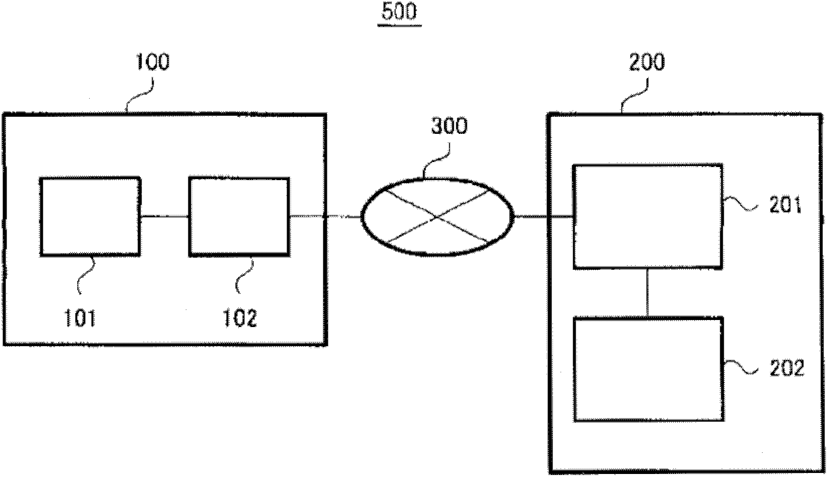
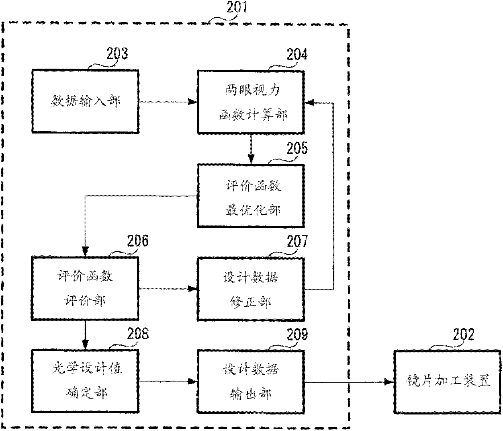
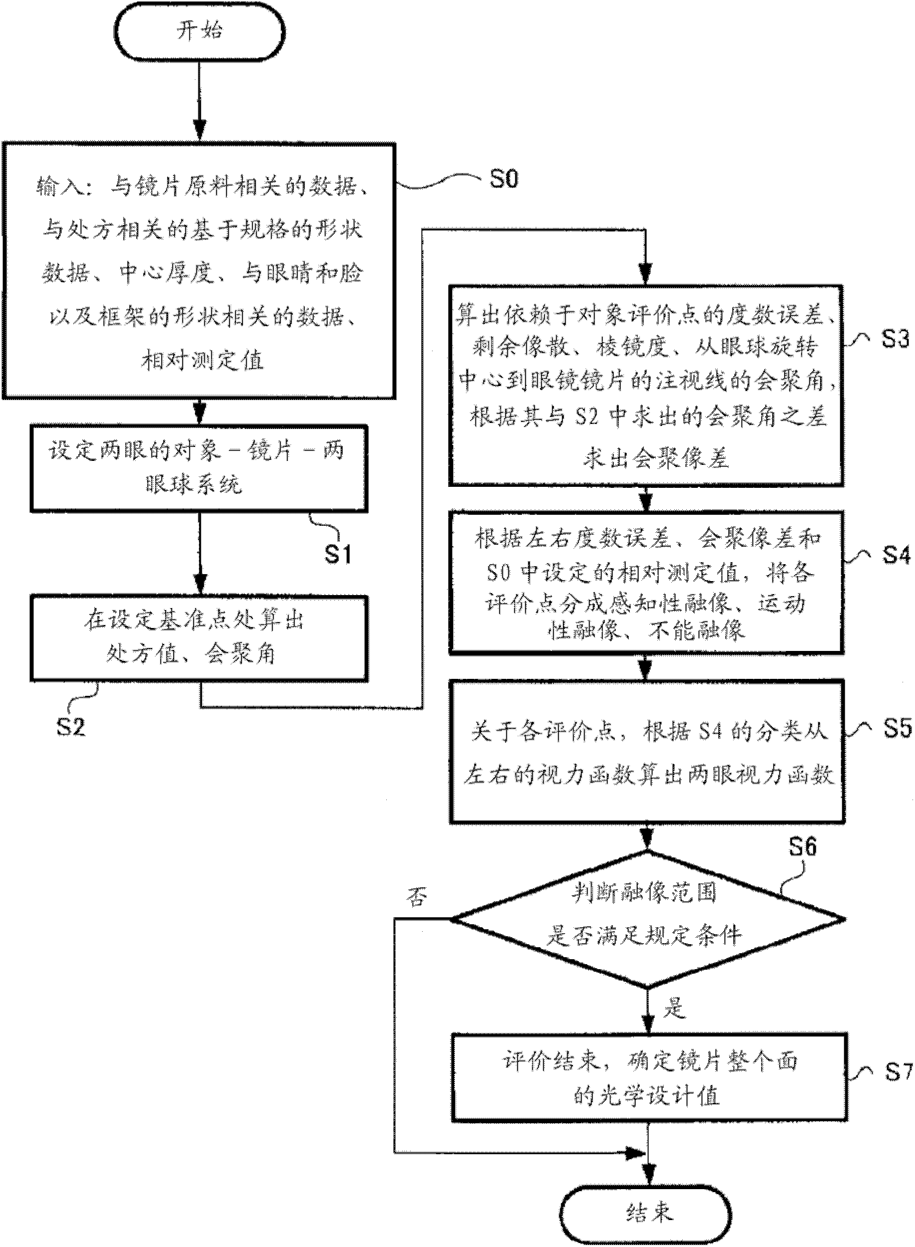

Image

  • Eyeglass lens evaluation method, eyeglass lens design method, eyeglass lens manufacturing method, eyeglass lens manufacturing system, and eyeglass lens
  • Eyeglass lens evaluation method, eyeglass lens design method, eyeglass lens manufacturing method, eyeglass lens manufacturing system, and eyeglass lens
  • Eyeglass lens evaluation method, eyeglass lens design method, eyeglass lens manufacturing method, eyeglass lens manufacturing system, and eyeglass lens

Examples


Embodiment 1

[0281] In this example, a calculation example related to binocular vision in the case where both the left and right spectacle lenses have a spherical power of -4D and an astigmatic power of 0D is given. Calculated as Figure 18 ~ Figure 21 shown. This example is an evaluation example of a single-focal spectacle lens, and repeated calculations for optimization were not performed. As the object, the hemispherical surface in front of the eye with an infinite radius centered on the origin 1 of the observation direction in the coordinate system described in the above-mentioned embodiment is used. That is to say, when hyperopia is evaluated. Spectacle lenses are general-purpose double-sided aspheric lenses, and are well corrected by the visual acuity function of Patent Document 2. In order to clarify the effect of the evaluation method of the present invention, the forward tilt angle, the pitch angle, and the eccentricity of the lens are set to zero. The distance from the cornea...

Embodiment 2

[0283] (2) Example 2 (the example where the difference between the left and right spherical powers is -2D or more)

[0284]As Example 2, evaluation of spectacle lenses generally defined as anisometropia (left and right - 2D or more) was performed. In this example, the spherical power of the spectacle lens for the right eye is -4D, and the astigmatism power is 0D, that is, the spectacle lens for the right eye is the same as the lens used in Example 1 above. On the other hand, the spherical power of the spectacle lens for the left eye was -6D, the astigmatism power was 0D, and the other conditions were the same as those in Example 1 above. This example is also an evaluation example of spectacle lenses, and repeated calculations for optimization were not performed. Figure 22 is the convergence aberration in the plane-parallel direction, Figure 23 is the convergence aberration in the direction perpendicular to the surface, Figure 24 Is the gaze through the glasses lenses of ...

Embodiment 3

[0286] (3) Embodiment 3 (example of a pitch angle of 20 degrees)

[0287] As Example 3, the convergence aberration when the lens frame has a pitch angle was calculated. The spherical power, astigmatic power, and other conditions are the same as those of the lenses used in Example 1 above, and the pitch angle was set to 20 degrees in order to evaluate the effect of the pitch angle. This example is also an evaluation example of spectacle lenses, and repeated calculations for optimization were not performed. Figure 26 is the convergence aberration in the plane-parallel direction, Figure 27 is the convergence aberration in the direction perpendicular to the surface, Figure 28 Is the gaze through the glasses lenses of both eyes, Figure 29 is the binocular visual acuity function value, and the unit is the same as Figure 18 ~ Figure 21 same.

[0288] In this example, the feature is Figure 26 The plane-parallel direction of the convergence aberration shown is the same as ...


PUM


Abstract

The invention relates to an eyeglass lens evaluation method, an eyeglass lens design method, an eyeglass lens manufacturing method, an eyeglass lens manufacturing system and an eyeglass lens. With respect to the evaluation of a custom-made eyeglass lens using a binocular vision function, the binocular vision function includes as a factor a measurement value which requires at least one of or both of the positive relative convergence and the negative relative convergence, of the positive relative convergence, the negative relative convergence, the positive relative accommodation, the negative relative accommodation, and the vertical fusional vergence.

Description

technical field [0001] The present invention relates to a spectacle lens evaluation method for performance evaluation when designing or manufacturing spectacle lenses, a spectacle lens design method using the spectacle lens evaluation method, a spectacle lens manufacturing method, a spectacle lens manufacturing system, and spectacle lenses. Background technique [0002] When evaluating and designing spectacle lenses, various evaluation methods and design methods have been proposed in order to obtain an optimum field of vision, and in particular, technologies focusing on visual acuity while wearing spectacle lenses have been proposed. For example, Patent Document 1 (WO2002 / 088828 A) discloses a technique for designing spectacle lenses using a visual acuity function. Patent Document 2 (WO2004 / 018988 A) describes spectacle lenses designed in consideration of the chromatic aberration of the visual acuity function. Here, the visual acuity function is a function representing visu...

Claims


Application Information

Patent Timeline
Patent Type & Authority Applications(China)
IPC IPC(8): G02C7/02G01M11/02G02C13/00
CPCG01M11/0257G02C7/027G02C7/061G02C2202/06
Inventor 山梶哲马
Owner HOYA CORP
Learn More