Full-cloth-width patient transferring bed surface and motion control structure thereof

A technology for picking up and delivering beds and patients, which is applied in the fields of hospital beds, medical science, and hospital equipment. It can solve the problems that the bed panel movement space is greatly affected, the effective working bed surface is small, and the driving structure is complicated, so as to increase the effective working area and move. Smooth, driving force delivery Direct and reliable results

Inactive Publication Date: 2012-03-14
CHANGSHU HUICHENG ELECTROMECHANICAL TECH
View PDF3 Cites 5 Cited by
  • Summary
  • Abstract
  • Description
  • Claims
  • Application Information

AI Technical Summary

Problems solved by technology

However, the driving structure of this electric transfer bed is complex (generally including the bed panel pushing system, the bed surface cloth synchronous scrolling system, the cloth rolling roller clutch system,

Method used


Image

  • Full-cloth-width patient transferring bed surface and motion control structure thereof
  • Full-cloth-width patient transferring bed surface and motion control structure thereof
  • Full-cloth-width patient transferring bed surface and motion control structure thereof

Examples


Embodiment Construction

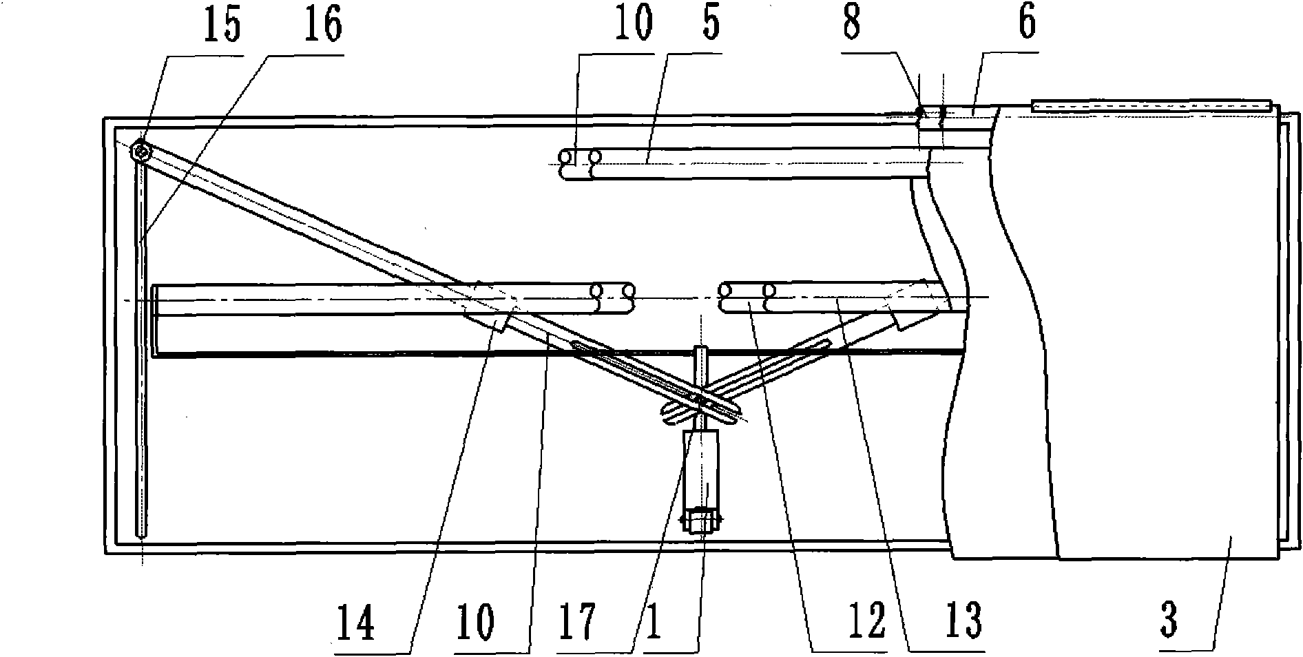
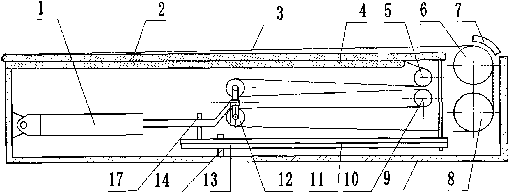
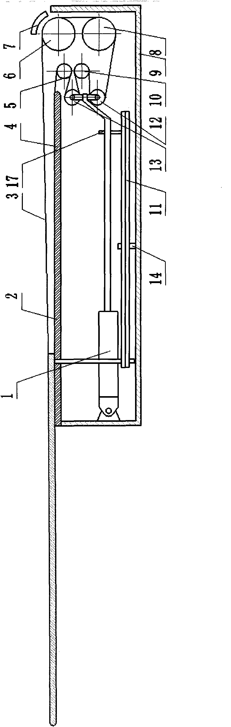
[0014] figure 1 Among them, the electric push rod or electro-hydraulic push rod (1) can do linear telescopic movement, and the sliding fulcrum (14) has a transfer pair with the bed frame (4), and a linear movement pair with the paddle bar (11). The paddle rod (11) is driven to rotate around the sliding fulcrum (14) by pushing the paddle pin (17), forming a lever structure. The two paddle rods arranged symmetrically have long slots at one end of the push rod push paddle pin (17), in which the push paddle pin (17) slides. The other end of the paddle bar (11) is fixedly connected to the bottom of the bed panel (2) through the rotating pair, thereby driving the bed panel (2) to expand and contract. Electric push rods or electro-hydraulic push rods (1) are connected together through rotating pairs at both ends of the moving rollers, thereby ensuring that the moving rollers move in the direction opposite to the direction in which the bed panel moves. The distance from the sliding ...


PUM


Abstract

The invention discloses a full-cloth-width patient transferring bed surface and a motion control structure thereof, belonging to the technical field of medical auxiliary equipment. The full-cloth-width patient transferring bed surface consists of full-width bed surface cloth, a paddle driving system, a bed panel, upper and lower guide rollers, upper and lower reversing rollers, upper and lower movable rollers, a roller pressing device and a bed frame, wherein the annular full-width bed surface cloth is wound on the bed panel, the guide rollers, the reversing rollers and the movable rollers, so that a surrounding structure is formed by the bed surface cloth; the paddle driving system is used for driving the bed panel to stretch and retract, and is matched with the roller pressing device, so that the bed surface cloth is static relative to a patent during patient transferring, and transferring is facilitated; and meanwhile, a pull rod in the paddle driving system is used for driving themovable rollers to compensate for the bed surface cloth, so that the aim of transferring a patient is fulfilled. The invention aims to effectively simplify the driving structure of the conventional patient transferring bed surface, reduce a prime mover by linking and fulfill the aim of achieving a compact structure and saving energy. By providing a cloth width compensating function, all-bed-surface cloth coverage is realized, so that the operating safety and attractiveness are enhanced.

Description

Technical field [0001] The invention relates to a full-width patient transfer bed surface and a motion control structure thereof, belonging to the technical field of medical auxiliary equipment. Background technique [0002] At present, there are two types of known patient transfer beds: a kind of manual mode, that is, the process of receiving and sending patients is realized by manual mode. This pick-up bed has a simple structure and generally has no bed cloth. The process of picking up and sending patients is realized through the expansion and contraction of the bed panel. During this period, the operator needs to actively intervene in the patient's position to assist in the transfer of the bed panel. This way is labor-intensive and may sometimes cause injury to the patient. The other is the electric method, that is, the process of picking up and sending patients is realized by electric means. Generally, there is a bed cloth on the bed panel. However, the driving struc...

Claims


Application Information

Patent Timeline
IPC IPC(8): A61G7/05
Inventor 臧铁钢朱建江
Owner CHANGSHU HUICHENG ELECTROMECHANICAL TECH
Why Eureka
Try Eureka