Surfactant foam flushing technology for polychlorinated biphenyls (PCBs) polluted soil repair

A technology for polluted soil and foam, applied in the field of remediation, can solve the problem of ineffective removal of pollutants, gas or waste of foaming agent, etc., and achieve the effects of uniform size, low cost and improved sweep efficiency.

Inactive Publication Date: 2012-03-14
陈家军 +2
View PDF3 Cites 18 Cited by
  • Summary
  • Abstract
  • Description
  • Claims
  • Application Information

AI Technical Summary

Problems solved by technology

However, since the foam used in this technology is naturally generated in the pores of the medium to be repaired, the characteristics of the foam during the repair process are basically uncontrolled, so that the flushing fluid can not only remove pollutants efficiently, but also cause gas or foaming agent waste
As we all know, the core of the foam flushing technology is to reduce the flow velocity of the flushing liquid and improve the overall sweep efficiency, and the main factors affecting the foam fluidity are the pore

Method used


Image

  • Surfactant foam flushing technology for polychlorinated biphenyls (PCBs) polluted soil repair
  • Surfactant foam flushing technology for polychlorinated biphenyls (PCBs) polluted soil repair
  • Surfactant foam flushing technology for polychlorinated biphenyls (PCBs) polluted soil repair

Examples


Embodiment 1

[0027] Embodiment 1 (conversion gas content):

[0028] Traditional foam flushing conditions: directly use nitrogen compressed bottle to supply gas, peristaltic pump to supply liquid, and inject the gas-liquid mixture into the polluted sand.

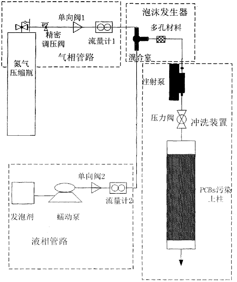
[0029] Flushing technology of the present invention, with reference to attached figure 1 , the foam is prepared by the device for preparing heterotopic foam, the device includes a nitrogen compression bottle, a pressure reducing valve, a precision pressure regulating valve, a one-way valve, a flow meter 1, a peristaltic pump, a flow meter 2, a gas-liquid mixing chamber, and a porous material (Consolidated sand core, average pore diameter 0.1mm). In the gas phase pipeline, a precision pressure regulating valve is installed after the pressure reducing valve, and then connected to the check valve 1 and the flow meter 1; in the liquid phase pipeline, the peristaltic pump is connected to the check valve 2 and the flow meter 2.

[0030] Use 7...

Embodiment 2

[0037] Embodiment 2 (conversion foam particle size)

[0038] Traditional foam flushing conditions: Directly use compressed air bottle to supply air, injection pump to supply liquid, and inject the air-liquid mixture into the polluted sand.

[0039] Flushing technology of the present invention, with reference to attached figure 1 , the foam is prepared by the device for preparing heterotopic foam, the device includes a nitrogen compression bottle, a pressure reducing valve, a precision pressure regulating valve, a one-way valve, a flow meter 1, a peristaltic pump, a flow meter 2, a gas-liquid mixing chamber, and a porous material (Metal aeration head, average aperture 0.1mm and 0.4mm). In the gas phase pipeline, a precision pressure regulating valve is installed after the pressure reducing valve, and then connected to the check valve 1 and the flow meter 1; in the liquid phase pipeline, the peristaltic pump is connected to the check valve 2 and the flow meter 2.

[0040] Use ...


PUM

PropertyMeasurementUnit
Particle sizeaaaaaaaaaa

Abstract

The invention discloses a foam flushing technology for polychlorinated biphenyls (PCBs) polluted soil. The technology comprises the following steps of: manufacturing ectopic foam by using surfactant and nitrogen, controlling the property of the foam by controlling the gas-liquid ratio and the particle diameter of the foam, and performing foam flushing in a pressed injection mode by using the foam, wherein the gas-liquid ratio of the foam is 100:35-100:0.2, the particle diameter is 10 to 3,500 microns, and the injection pressure is 0.1 to 15 meters water columns. Compared with the conventional foam flushing technology, the technology has the advantages of improving the wave and the efficiency of a flushing fluid in a soil medium by controlling the property of the foam and finally improving the removal efficiency of the PCBs.

Description

technical field [0001] The invention relates to a repairing technology for polychlorinated biphenyls (PCBs) polluted soil, in particular to a method for repairing organic polluted soil by using surfactant foam flushing technology. Background technique [0002] PCBs are a kind of natural or artificial substances with persistence, bioaccumulation, semi-volatility, long-distance migration and high toxicity, which can migrate in the atmospheric environment for a long distance and can be deposited on the earth. Synthetic organic pollutants. Due to the strong lipophilicity of PCBs, it is difficult to remediate the contaminated media once the soil is polluted. [0003] Surfactant flushing is one of the methods recommended by the U.S. Environmental Protection Agency for the in-situ treatment of hydrophobic organic pollutants in soil and groundwater pollution. There are two main mechanisms: one is to use the solubilization of surfactant micelles to increase the solubility of pollut...

Claims


Application Information

Patent Timeline
IPC IPC(8): B09C1/08
Inventor 陈家军王浩
Owner 陈家军
Why Eureka
Try Eureka