Luminous device and illuminator using luminous device
A technology for light-emitting devices and light sources, which is applied to lighting devices, components of lighting devices, optical elements used to change the spectral characteristics of emitted light, etc., can solve problems such as human injury, environmental pollution, and lack of long afterglow characteristics. Achieve high luminous efficiency, good color rendering, and improve light utilization efficiency.
- Summary
- Abstract
- Description
- Claims
- Application Information
AI Technical Summary
Problems solved by technology
Method used
Image
Examples
Embodiment 1
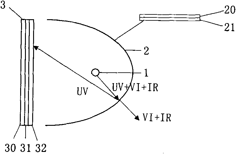
[0047] figure 1 It is a structural diagram of the light emitting device of Example 1 of the present invention. exist figure 1 Among them, the light-emitting device 5 includes a high-pressure mercury lamp 1 as a light source, an ultraviolet cutoff filter 2 for reflecting ultraviolet light emitted by the high-pressure mercury lamp 1, passing visible light and infrared light, and ultraviolet light reflected by the ultraviolet cutoff filter 2. A wavelength conversion element 3 that converts to visible light. exist figure 1 Middle UV, VI and IR represent ultraviolet light, visible light and infrared light, respectively.
[0048] The typical structure of the high-pressure mercury lamp 1 is to seal two tungsten electrodes in a transparent quartz glass tube with a high melting point, and fill the tube with argon gas of about 2.5-4.0 kPa and a certain amount of mercury. The tungsten electrode and the quartz glass tube are hermetically sealed with a molybdenum foil. Once a high ...
Embodiment 2
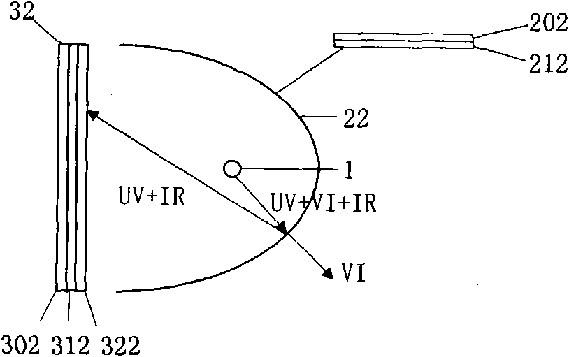
[0054] figure 2 is a structural diagram of a light-emitting device according to Example 2 of the present invention. exist figure 2 Among them, the difference from the structure of Example 1 is that the UV cut filter film 212 is replaced by the UV cut filter film 212, and the wavelength conversion layer 32 is replaced by the wavelength conversion layer 322. The difference between the two wavelength conversion layers lies in the luminescent The materials are different. The transmittance characteristics of the ultraviolet and infrared cut-off filter 22 are as follows: Figure 8 shown by Figure 8 It can be seen that it can reflect ultraviolet light and infrared light well, and allow visible light to pass through.
[0055] The working process of the light-emitting device 5 is as follows: the light emitted by the high-pressure mercury lamp 1 is irradiated on the ultraviolet and infrared cut-off filter film 212, and the ultraviolet and infrared cut-off filter film 212 allows v...
Embodiment 3
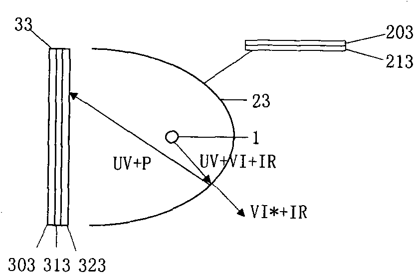
[0057] image 3 is a structural diagram of a light-emitting device according to Example 3 of the present invention. exist image 3 Among them, the difference with the structure of Example 1 is that the ultraviolet cut-off filter film 21 is replaced by the purple short-wavelength cut-off filter film 213, and the wavelength conversion layer 32 is replaced by the wavelength conversion layer 323. The difference between the two wavelength conversion layers lies in the adopted Luminescent materials are different. Here, the purple short-wavelength cut-off filter film 213 refers to a short-wavelength cut-off filter film with a semi-transmission position (T50%) of 415-435 nm. exist image 3 Among them, P represents purple light, and VI* represents visible light and infrared light with a wavelength longer than purple light. The transmittance characteristics of the purple short-wavelength cut-off filter 23 are as follows: Figure 9 shown by Figure 9 It can be seen that it can refl...
PUM
 Abstract
Description
Claims
Application Information
 - R&D
- Intellectual Property
- Life Sciences
- Materials
- Tech Scout
- Unparalleled Data Quality
- Higher Quality Content
- 60% Fewer Hallucinations
Browse by: Latest US Patents, China's latest patents, Technical Efficacy Thesaurus, Application Domain, Technology Topic, Popular Technical Reports.
© 2025 PatSnap. All rights reserved.Legal|Privacy policy|Modern Slavery Act Transparency Statement|Sitemap|About US| Contact US: help@patsnap.com


