
Loop heat pipe

A loop heat pipe and pipeline technology, used in circuits, indirect heat exchangers, lighting and heating equipment, etc., can solve problems such as drying up, affecting heat transfer efficiency, burning loss, etc., to achieve the effect of improving performance

Inactive Publication Date: 2012-03-14
FU ZHUN PRECISION IND SHENZHEN +1
View PDF7 Cites 28 Cited by
  • Summary
  • Abstract
  • Description
  • Claims
  • Application Information

AI Technical Summary

Problems solved by technology

If the capillary structure is too thin, the liquid working medium that the capillary structure can absorb is less, so it is easy to dry up or even burn out, which will affect the working performance of the heat pipe; if the capillary structure is too thick, the reaction time for the working medium in it to evaporate will be long, which will affect the heat transfer. Thermal efficiency

Method used


Image

  • Loop heat pipe
  • Loop heat pipe
  • Loop heat pipe

Examples


Embodiment Construction

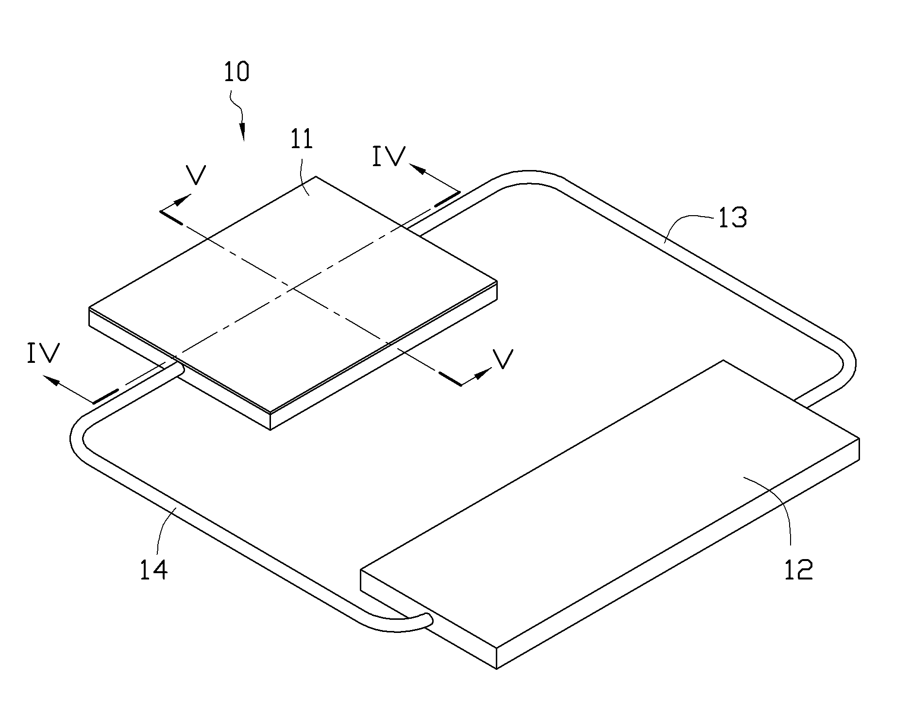
[0018] Please refer to figure 1 , The loop heat pipe 10 in the first embodiment of the present invention includes an evaporator 11 , a condenser 12 , a vapor line 13 and a liquid line 14 .

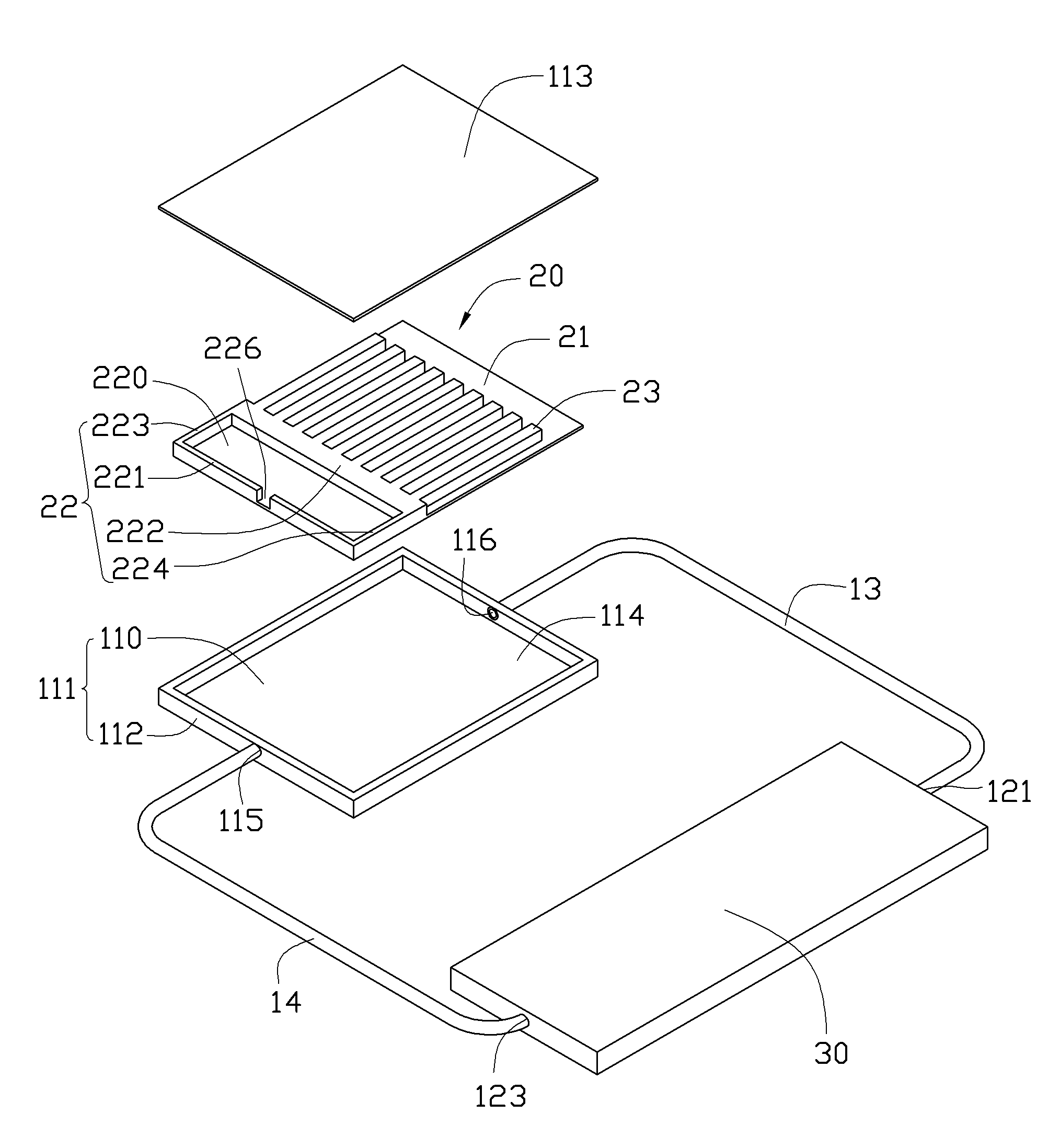
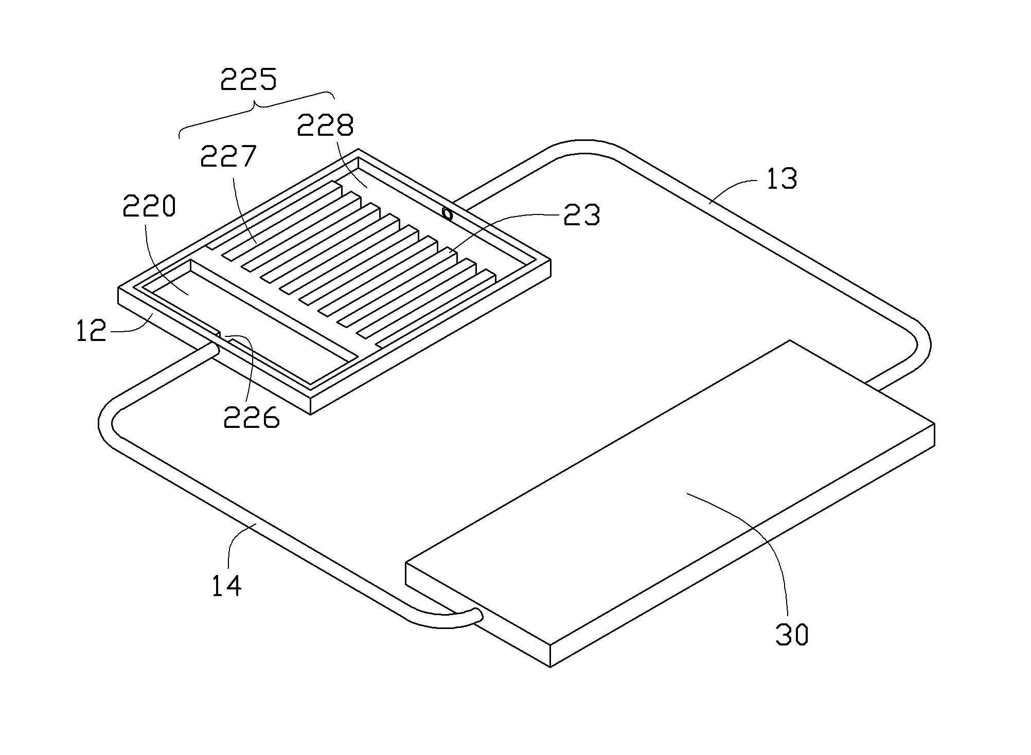
[0019] Please also refer to figure 2 , the evaporator 11 is rectangular and includes a base 111 , a capillary structure 20 accommodated in the base 111 and a cover plate 113 covering the base 111 . The base 111 includes a rectangular bottom plate 110 and a side plate 112 extending upward from a periphery of the bottom plate 110 . The cover plate 113 covers the top of the side plate 112 , and the bottom plate 110 , the side plate 112 and the cover plate 113 together form a receiving space 114 for accommodating the capillary structure 20 . An evaporator inlet 115 connected to one end of the liquid line 14 and an evaporator outlet 116 connected to one end of the vapor line 13 are respectively provided on the side plates 112 at the left and right ends of the evaporator 11 .

[0020] The ca...


PUM


Abstract

The invention discloses a loop heat pipe. The loop heat pipe comprises an evaporation part, a condensation part, a vapor pipeline and a liquid pipeline, wherein the vapor pipeline and the liquid pipeline are arranged between the evaporation part and the condensation part and connect the evaporation part and the condensation part into a loop; a working medium is filled in the loop; a capillary structure is arranged in the evaporation part, and comprises a flat plate part pasted on the bottom surface of the evaporation part, a supporting wall extending from the flat plate part to the top surface of the evaporation part, and a plurality of bar-shaped parts extending from the side surface of the supporting wall to one side of the vapor pipeline; the supporting wall and the bar-shaped parts separate the space in the evaporation part into a liquid storage chamber communicated with the liquid pipeline, and a vapor chamber communicated with the vapor pipeline; and a vapor groove communicated with the vapor chamber is formed between two adjacent bar-shaped parts.

Description

technical field [0001] The invention relates to a heat transfer element, in particular to a loop heat pipe. Background technique [0002] With the continuous improvement of the power of electronic components such as central processing units, the problem of heat dissipation has been paid more and more attention by people. A loop heat pipe (LHP) is used as an effective heat transfer element in the field of heat dissipation due to its efficient heat conduction performance. [0003] Generally, the loop heat pipe includes an evaporator, a condenser, and a vapor line and a liquid line disposed between the evaporator and the condenser. The vapor pipeline and the liquid pipeline connect the evaporating part and the condensing part to form a circuit, and the circuit is filled with working medium. The inner surface of the evaporating part is pasted with a capillary structure, and a cavity capable of storing working medium is arranged inside. When the evaporation part of the loop he...

Claims


Application Information

Patent Timeline
Patent Type & Authority Applications(China)
IPC IPC(8): F28D15/04H05K7/20
CPCF28D15/0266F28D15/043H01L23/427H01L2924/0002H01L2924/00
Inventor 王德玉许超胡江俊
Owner FU ZHUN PRECISION IND SHENZHEN
Learn More