Variable-diameter-tube drilling fluid rheology measuring method

A measurement method and drilling fluid technology, applied in the direction of direct current flow characteristics measurement, etc., can solve the problems of long time, difficulty in rapid measurement of drilling fluid rheological changes, and inability to meet continuous measurement of drilling fluid rheology, etc., to improve measurement efficiency , Realize the effect of online measurement

Active Publication Date: 2012-03-14
CHINA PETROCHEMICAL CORP +3
View PDF5 Cites 31 Cited by
  • Summary
  • Abstract
  • Description
  • Claims
  • Application Information

AI Technical Summary

Problems solved by technology

The current conventional drilling fluid rheological testing methods, whether it is the rotary method or the capillary method, cannot meet the needs of continuous measurement of drilling fluid rheology.
Because the conventional capillary method can only measure the apparent viscosity under a single velocity gradient, or the flow velocity must be changed successively to achieve rheological measurement, it takes a long time to measure a set of rheological curves, so it is difficult to change the rheologica

Method used


Image

  • Variable-diameter-tube drilling fluid rheology measuring method
  • Variable-diameter-tube drilling fluid rheology measuring method
  • Variable-diameter-tube drilling fluid rheology measuring method

Examples


Embodiment 1

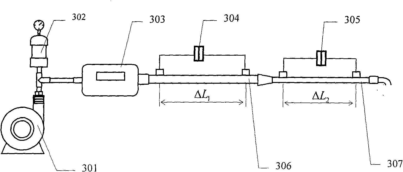
[0040] Example 1: In image 3 In the embodiment of the present invention, a constant flow pump (301) is combined with a damper (302) to provide a pulse-free flow rate, and a flow meter (303) is used to accurately measure the flow rate q of the fluid; 1 and r 2 Two capillary tubes (306 and 307) are connected in series to form a variable diameter tube to achieve different flow velocities v m (m=1, 2); according to the flow velocity v of each section of reducer m Calculate the velocity gradient γ on the wall of the two reducing pipes using the diameter of each reducing pipe 1 and gamma 2 ; Use differential pressure gauges (304 and 305) to measure the first section and the second section reducing pipe at ΔL 1 and ΔL 2 Pressure loss Δp in the tube 1 and Δp 2 , according to the radius r of the two-section reducer 1 and r 2 , length ΔL 1 and ΔL 2 , and the pressure loss Δp 1 and Δp 2 Calculation of the shear stress value τ on the pipe wall of the two sections 1 and τ ...

Embodiment 2

[0041] Example 2: In Figure 5 In the embodiment, a constant flow pump (501) is combined with a damper (502) to provide a pulse-free flow, and a flow meter (503) is used to accurately measure the flow q of the fluid; 1 、r 2 、r 3 、r 4 、r 5 、r 6 The six capillary tubes (516, 517, 518, 519, 520, 521) form variable diameter tubes to achieve different flow velocities v n (n=1, 2, 3, 4, 5, 6) and velocity gradient γ 1 , γ 2 , γ 3 , γ 4 , γ 5 , γ 6 ; Use pressure gauges (504 and 505) to measure the ΔL in the first capillary 1 Pressure loss Δp in the tube 1 , use pressure gauges (506 and 507) to measure the ΔL of the second capillary 2 Pressure loss Δp in the tube 2 , use pressure gauges (508 and 509) to measure ΔL in the third section capillary 3 Pressure loss Δp in the tube 3 , use pressure gauges (510 and 511) to measure the internal ΔL of the fourth section capillary 4 Pressure loss Δp in the tube 4 , use pressure gauges (512 and 513) to measure the internal ΔL o...


PUM


Abstract

The invention relates to a variable-diameter-tube drilling fluid rheology measuring method which is especially suitable for on-line detections of in situ drilling fluid rheology. The method comprises steps that: a variable-diameter-tube system is composed of 2 to 20 segments of tubules with different diameters, wherein the tubules are connected in series; a stable flow rate is provided for the variable-diameter-tube system by using a constant flow pump and a buffer; current velocities in different diameter segments of the variable-diameter-tube system are calculated according to the flow rate and the cross section areas of the tubules; velocity gradients in different diameter segments are calculated according to the current velocities and diameters of the different diameter segments of the variable-diameter-tube system; pressure losses in different diameter segments of the variable-diameter-tube system are detected by using a differential pressure gauge; shear stress values of the different diameter segments of the variable-diameter-tube system are calculated according to the pressure losses; and rheology parameters such as plastic viscosity, dynamic shearing force, flow pattern index, and consistency coefficient of the measured drilling fluid can be calculated according to the shear stress values under different velocity gradients. With the method provided by the invention, drilling fluid rheology and variation conditions thereof can be measured in real-time without changing the flow rate.

Description

technical field [0001] The invention relates to a method for measuring the rheological properties of drilling fluids with variable diameter tubes, which is especially suitable for on-line detection of rheological properties of drilling fluids on site. Background technique [0002] Rheology is a science that studies material flow and deformation, and the study of drilling fluid rheology is an important aspect of rheology. The rheology of drilling fluid generally includes fluid viscosity, static shear force, dynamic shear force and shear thinning properties. The mastery and adjustment of these rheological properties have a very important relationship with improving drilling speed and downhole safety. The rheology of the drilling fluid is related to (1) the ability of the drilling fluid to carry cuttings and clean the borehole; (2) the suspension capacity; (3) the stabilizing effect on the well wall; (4) the optimal design of the drilling parameters—the water horsepower of the...

Claims


Application Information

Patent Timeline
IPC IPC(8): G01N11/04G01N11/08
Inventor 刘保双李公让王忠杰马云谦唐代绪何兴贵隋旭强
Owner CHINA PETROCHEMICAL CORP
Why Eureka
Try Eureka