
Battery pack for practical low-power mode current detection and method of detecting excessive current

A detection method and battery pack technology, applied in battery overcurrent protection, battery overdischarge protection, battery disconnection circuit, etc., can solve problems such as temperature rise, power loss increase, and overcurrent time delay that cannot be ignored.

Active Publication Date: 2012-03-14
PANASONIC ENERGY CO LTD MORIGUCHI SHI
View PDF3 Cites 2 Cited by
  • Summary
  • Abstract
  • Description
  • Claims
  • Application Information

AI Technical Summary

Problems solved by technology

[0006] However, when the resistance value of the current detection resistor is increased to expand the setting range of the overcurrent, there is a problem that the power loss generated in the current detection resistor increases during normal charge and discharge, and the overcurrent caused by heat generation cannot be ignored. temperature rise caused by
In addition, similar to the detection of the charge and discharge current in normal charge and discharge control, for example, when the voltage at both ends of the current detection resistor after the analog-to-digital conversion is detected by software as a voltage corresponding to the overcurrent, since the The detection on the time series is eliminated, so there is a problem that the detection of overcurrent is delayed in time

Method used


Image

  • Battery pack for practical low-power mode current detection and method of detecting excessive current
  • Battery pack for practical low-power mode current detection and method of detecting excessive current
  • Battery pack for practical low-power mode current detection and method of detecting excessive current

Examples


Embodiment Construction

[0054] Hereinafter, the present invention will be described in detail based on the drawings showing the present embodiment.

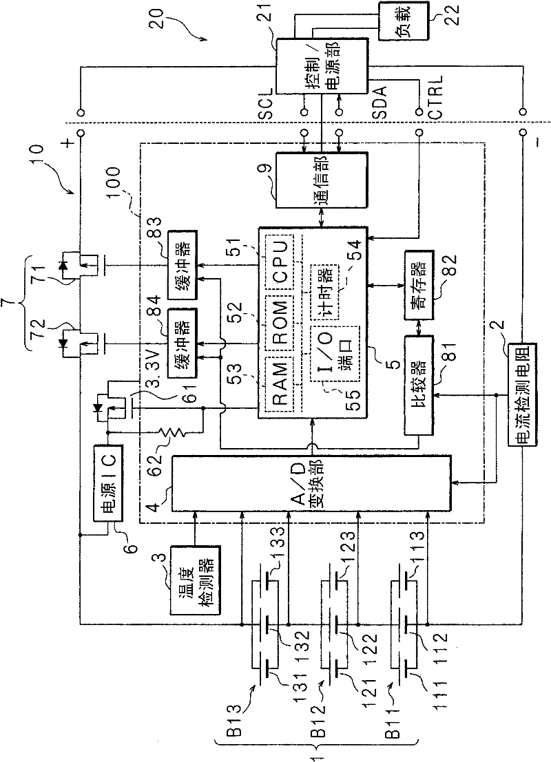
[0055] figure 1 It is a block diagram showing a configuration example of the assembled battery according to the embodiment of the present invention. 10 in the figure is a battery pack, and the battery pack 10 is detachably mounted on a load device 20 such as a personal computer (PC), a portable terminal, or the like. The assembled battery 10 includes a battery 1 in which battery blocks B11, B12, and B13 are sequentially connected in series, wherein the battery blocks B11, B12, and B13 are battery cells 111, 112, 113, 121, and 122 composed of lithium-ion secondary batteries. , 123, 131, 132, 133 are connected in parallel in turn. The battery 1 has the positive electrode of the battery block B13 and the negative electrode of the battery block B11 as a positive terminal and a negative terminal, respectively.

[0056] The voltages of the battery blocks B...


PUM


Abstract

In a battery pack 10 control section 5 low-power mode, a comparator 81 is used to detect the voltage across a 2.5 m[Omega] current detection resistor 2 connected in the battery 1 charging and discharging path. When the detected voltage exceeds a voltage (2.4 mV) that is lower than the voltage (50 mV) for detecting a 20 A first over-current in the non-low-power mode, that occurrence is recorded in a register 82. When the register 82 holds occurrence of the voltage being exceeded and when a CTRL signal indicating the load device 20 is in the low-power mode is input to an I / O port 55, the control section 5 CPU 51 detects a second over-current of approximately 1 A, switches OFF the cut-off devices 7, and sends advisory data from a communication section 9 to a control and power source section 21 in the load device 20.

Description

technical field [0001] The present invention relates to a battery pack that detects the voltage of a resistor inserted and connected to a charging and discharging circuit of a secondary battery to perform a predetermined operation, and an overcurrent detection method in the battery pack. Background technique [0002] When an overcurrent exceeding the allowable current flows through the battery pack containing the secondary battery, the secondary battery may generate heat, causing accidents such as fire and rupture. Therefore, in a conventional battery pack, a current detection resistor and a switching element are provided in the charging and discharging circuit of the secondary battery, and the switching element is turned off when the voltage detected by the current detecting resistor exceeds a predetermined value. [0003] For example, Patent Document 1 discloses a battery pack in which a discharge FET element and a current detection resistor are respectively inserted and c...

Claims


Application Information

Patent Timeline
Patent Type & Authority Applications(China)
IPC IPC(8): H01M10/48H01M10/44G01R19/165
CPCH02J7/0031H02J9/005Y04S20/20Y02B70/30H02J7/00304H02J7/00306
Inventor 松浦信一丰田和弘
Owner PANASONIC ENERGY CO LTD MORIGUCHI SHI
Learn More