
High-frequency conversion structure with rectangular-circular mode

A technology of mode conversion and high-frequency structure, which is applied in the microwave field, can solve the problems of difficulty in maintaining the size and phase, etc., and achieve the effect of solving the problem of energy input, simple and compact structure, and small mode distortion

Inactive Publication Date: 2012-03-14
INST OF ELECTRONICS CHINESE ACAD OF SCI
View PDF3 Cites 20 Cited by
  • Summary
  • Abstract
  • Description
  • Claims
  • Application Information

AI Technical Summary

Problems solved by technology

The main difficulty of this method is that within a certain bandwidth range, it is difficult for the two signals to maintain the same size and maintain a phase difference of 90° as the frequency changes.

Method used


Image

  • High-frequency conversion structure with rectangular-circular mode
  • High-frequency conversion structure with rectangular-circular mode
  • High-frequency conversion structure with rectangular-circular mode

Examples


Embodiment Construction

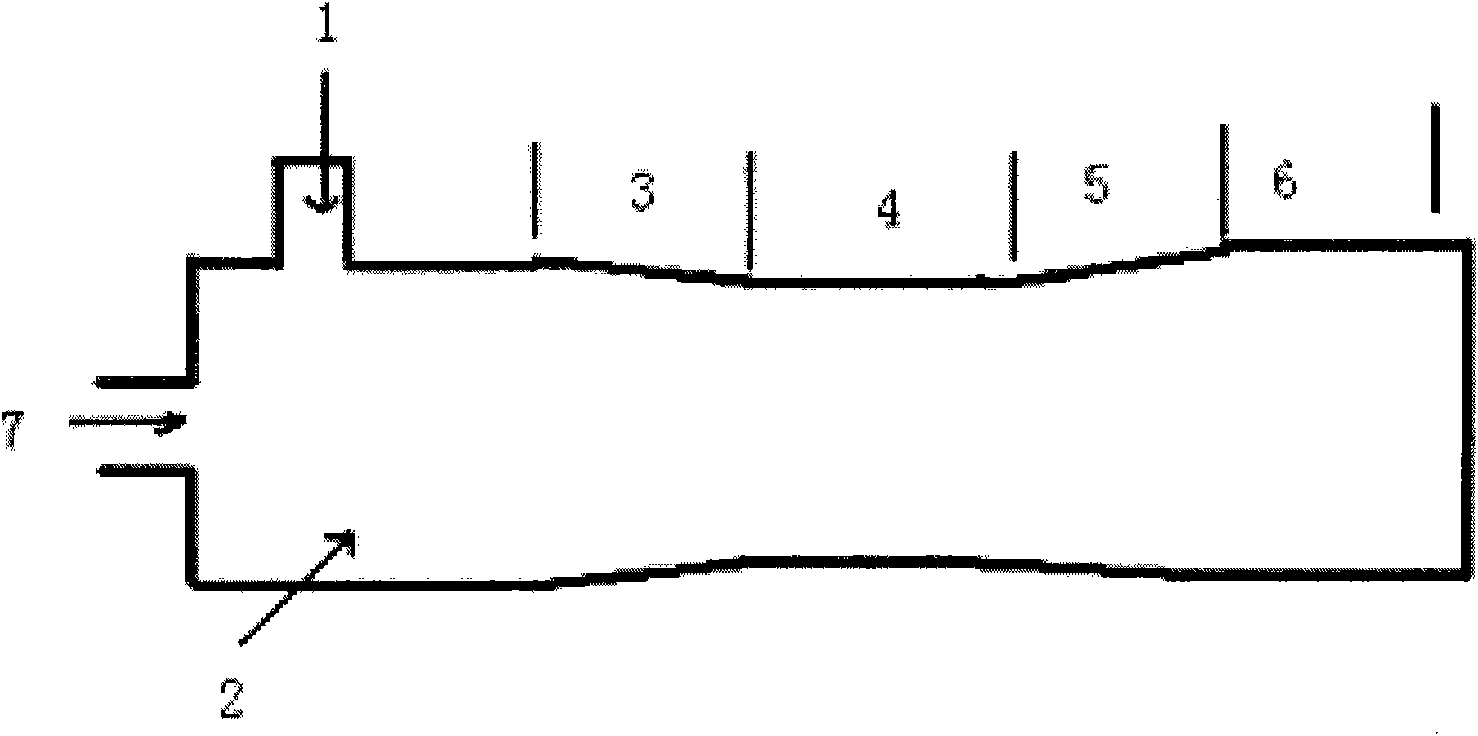
[0019] See figure 1 , is a rectangular mode conversion high-frequency structure of the present invention, specifically, the rectangular waveguide 1 is connected orthogonally to the circular waveguide 2, the circular waveguide 2 is connected to the tapered waveguide 3, and one end of the circular waveguide 2 is connected to the working mode TE11 mode cut-off The drift section 7 of the circular waveguide is also the electron beam channel. The tapered circular waveguide 3 is connected to the elliptical waveguide 4 , the elliptical waveguide 4 is connected to the tapered waveguide 5 , and the tapered waveguide 5 is connected to the circular waveguide 6 . Among them, the radius of the circular waveguide 2 is 2.72 mm, the length is 7.2 mm, the length of the tapered waveguide 3 is 5 mm, the length of the tapered waveguide 5 is 10 mm, the semi-major axis of the elliptical waveguide is 2.71 mm, and the semi-minor axis is 2.66 mm.

[0020] The linearly polarized signal is directly fed ...


PUM

PropertyMeasurementUnit
Radiusaaaaaaaaaa
Lengthaaaaaaaaaa

Abstract

The invention discloses a high-frequency conversion structure with a rectangular-circular mode, relating to microwave technology. In the high-frequency conversion structure, a rectangular waveguide is orthogonally connected with a circular waveguide; one end of the circular waveguide is connected with a circular waveguide drift section which is closed aiming to a TE11 mode in an operating mode, and the other end of the circular waveguide is sequentially connected with a first tapering circular waveguide, an elliptical waveguide, a second tapering circular waveguide and an output circular waveguide; and the output circular waveguide is used for outputting waves in a TE11 circularly-polarized mode. The invention provides a novel method for converting rectangular waveguides from a TE10 linearly-polarized mode to an operating-mode TE11 circularly-polarized mode, therefore, the input coupling problem of a gyrotron amplifier is solved.

Description

technical field [0001] The invention belongs to the field of microwave technology, is applied to a high-power millimeter-wave gyrotron amplifier, and is a novel high-frequency structure for converting a rectangular waveguide polarization mode to a circular waveguide circular polarization mode. Background technique [0002] The gyrotron amplifier has the characteristics of high power, high gain and wide frequency band in the millimeter wave band. It has broad application prospects and development potential in radar imaging, electronic countermeasures, and anti-stealth target detection. It is a high-power microwave source that has attracted much attention. source of coherent radiation. The gyrotron amplifier amplifies the input microwave signal, which requires a broadband input coupling structure to input the input signal to the interaction circuit of the gyrotron amplifier to complete the conversion from the input mode to the working mode. Therefore, the broadband input coup...

Claims


Application Information

Patent Timeline
IPC IPC(8): H01P1/16
Inventor 徐寿喜刘濮鲲顾伟张世昌杜朝海
Owner INST OF ELECTRONICS CHINESE ACAD OF SCI
Learn More