Visual multifunctional intrauterine ring removing device production method and ring removing device produced by using same

A manufacturing method and a technology for a ring remover, which are applied in the field of ring removers, can solve the problem that the relative positions of the ring remover hook and the contraceptive ring cannot be found, the operation of visually extracting the contraceptive ring cannot be realized, and it is difficult to ensure the safety and effectiveness of the operation. Sex and other issues, to shorten the operation time, facilitate the combination and separation, and reduce medical accidents.

Inactive Publication Date: 2012-03-21
DONGGUAN MICROVIEW MEDICAL TECH
View PDF5 Cites 4 Cited by
  • Summary
  • Abstract
  • Description
  • Claims
  • Application Information

AI Technical Summary

Problems solved by technology

[0003] The existing devices and devices for extracting the IUD basically include two types: one is the blind extraction of the IUD, and the blind extraction of the IUD The hook is made of stainless steel wire with a diameter of 3 mm. The diameter of the steel wire at the head is 1.3 mm. Some hooks have a radius of about 1.8 mm. , in the process of removing the contraceptive ring, it is difficult to find the contraceptive ring, the operation time is long, it is easy to damage the normal tissue, and even cause uterine perforation, it is difficult to remove the contraceptive ring with serious incarceration, and other methods or even surgery are required. pain to the patient
The other is a device for visually extracting the birth control ring. Although it is operated under visible conditions, the design of the ring hook at t

Method used


Image

  • Visual multifunctional intrauterine ring removing device production method and ring removing device produced by using same
  • Visual multifunctional intrauterine ring removing device production method and ring removing device produced by using same
  • Visual multifunctional intrauterine ring removing device production method and ring removing device produced by using same

Examples


Embodiment

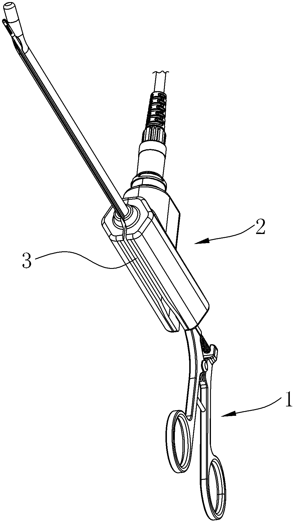
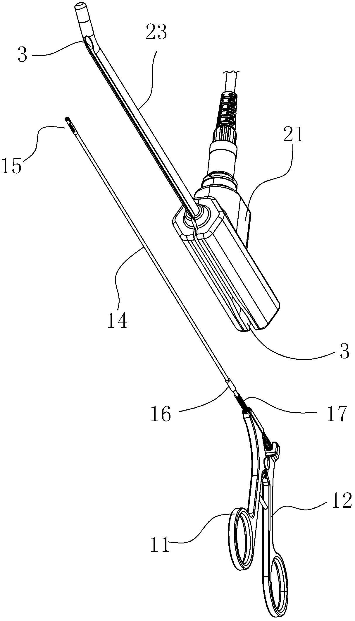
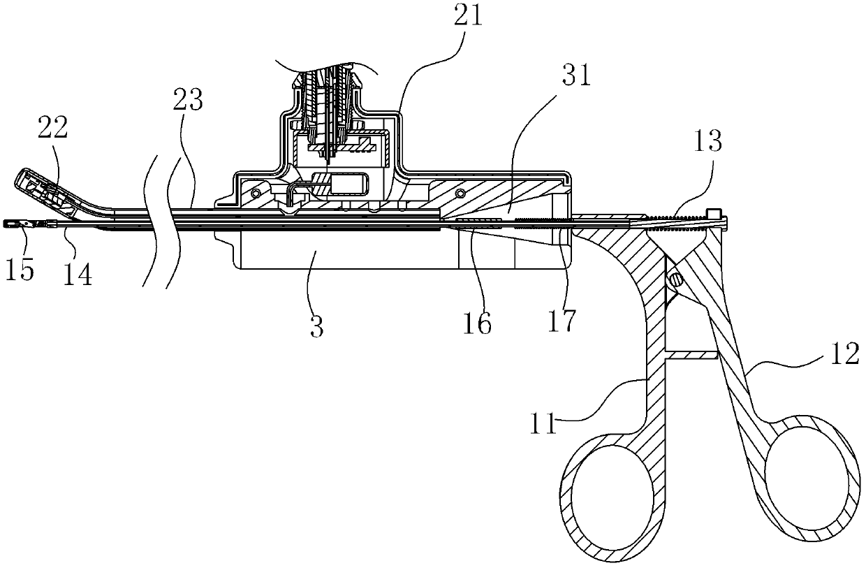
[0043] Example: see Figure 1 to Figure 3 , an embodiment of the present invention provides a method for manufacturing a visible multifunctional intrauterine ring remover, which includes the following steps:

[0044] (1) Prepare the required clamping instrument 1 according to different surgical operation requirements; the clamping instrument 1 in the above step (1) is a self-locking grasper. It is easy to use and easy to operate, ensuring the safety and effectiveness of the operation. The manufacturing method of the self-locking pliers specifically includes the following steps: (1.1) a fixed handle 11 is set; (1.2) a movable handle 12 is set; (1.3) a return spring 13 is set; (1.4) a pull rod is set; (1.5 ) is provided with a sleeve pipe 14; (1.6) a clamp head 15 is provided; (1.7) an adjustment limit ring 16 is provided; (1.8) the clamp head 15 is arranged on the front end of the sleeve pipe 14, and the sleeve pipe 14 The rear end of the handle is fixed on the fixed handle 1...


PUM


Abstract

The invention discloses a visual multifunctional intrauterine ring removing device production method, which comprises the following steps of: 1) preparing all required clamping apparatuses; and 2) setting an endoscope, wherein an apparatus passage is arranged on the endoscope. The invention additionally discloses a ring removing device produced by using the visual multifunctional intrauterine ring removing device production method. The method provided by the invention is simple, easy to realize and low-cost; the design of the ring removing device provided by the invention is ingenious, the structure is reasonable, and when the situation of an intrauterine device is observed, the clamping apparatuses can stretch into an uterus through the apparatus passage to take out the intrauterine device or clean foreign matters, the operation under a visual situation is realized, the surgery time can be greatly reduced, the pain of a patient is reduced, the dependence on the skill of a doctor is reduced and the accuracy and the success rate of a surgery are improved; and moreover, the endoscope and the clamping apparatuses can be conveniently combined and separated, the operation by the doctorand the cleaning and the disinfection of the endoscope and the clamping apparatuses are facilitated and the cross infection is avoided.

Description

technical field [0001] The invention relates to the technology in the field of medical devices, in particular to a method for manufacturing a visible multifunctional intrauterine ring remover and a ring remover implementing the method. Background technique [0002] The intrauterine device is a contraceptive device placed in the uterine cavity. Because most of the devices used in the early stage are ring-shaped, they are usually called birth control rings. The birth control ring has less interference to the whole body, acts on the local area, and does not affect fertility after being taken out. It has the advantages of safety, effectiveness, reversibility, simplicity, and economy. It is one of the most commonly used birth control devices. An IUD is usually placed in a woman's uterus to prevent pregnancy. Birth control rings come in various shapes, including circular rings, T-shaped rings, and triangular rings. The positions and shapes of birth control rings in the uterine ca...

Claims


Application Information

Patent Timeline
IPC IPC(8): A61F6/18
CPCA61B17/42A61B1/018A61B17/29A61B90/361A61B2017/00296A61F6/12
Inventor 沈振权勾成俊黄振宁
Owner DONGGUAN MICROVIEW MEDICAL TECH
Why Eureka
Try Eureka