Unmanned flying vehicle made with PCB

A printed circuit board, unmanned technology, applied in the field of unmanned aerial vehicles, can solve the problems of increasing the weight of the aircraft, reducing the flight efficiency, increasing the weight, etc., and achieving the effects of reducing the manufacturing cost, reducing the manufacturing cost, and reducing the total weight.

Inactive Publication Date: 2012-03-21
DREAM SPACE WORLD CORP
View PDF4 Cites 73 Cited by
  • Summary
  • Abstract
  • Description
  • Claims
  • Application Information

AI Technical Summary

Problems solved by technology

The structure of this unmanned aerial vehicle has the following disadvantages: the structure increases the weight of the aircraft, thereby reducing the flight efficiency, and the increase in weight causes the enlargement of the main board, battery and propeller, making the structure of the aircraft complex, thus Makes assembly difficult, leading to increased production costs
[0007] although figure 1 The scope of application of the unmanned aerial vehicle is endless, but since all the electronic modules are concentrated on the main board 10 located in the central position, it will undoubtedly increase the size of the main board 10 itself and complicate the circuit structure
Due to the above reasons, unmanned aerial vehicles as a whole have become larger and heavier, and excessive power is consumed when driving unmanned aerial vehicles, which requires more than a certain amount of power, and ultimately limits the types of engines that can be selected.
this limitation is a factor that increases the cost of making an unmanned aerial vehicle
Moreover, due to the complex circuit structure, if the heat generation of the motherboard 10 increases, it will cause frequent failures and misoperations.
[0008] In addition, if figure 1 As shown in , the transmission 30 is generally arranged on the frame 50. In order to control the transmission 30, the main board 10 and the transmission 30 need to be connected by cables, which increases the weight of the aircraft and complicates its structure.

Method used


Image

  • Unmanned flying vehicle made with PCB
  • Unmanned flying vehicle made with PCB
  • Unmanned flying vehicle made with PCB

Examples


Embodiment Construction

[0031] Embodiments of the present invention will be described in detail below with reference to the accompanying drawings, so that those skilled in the art of the present invention can easily implement them.

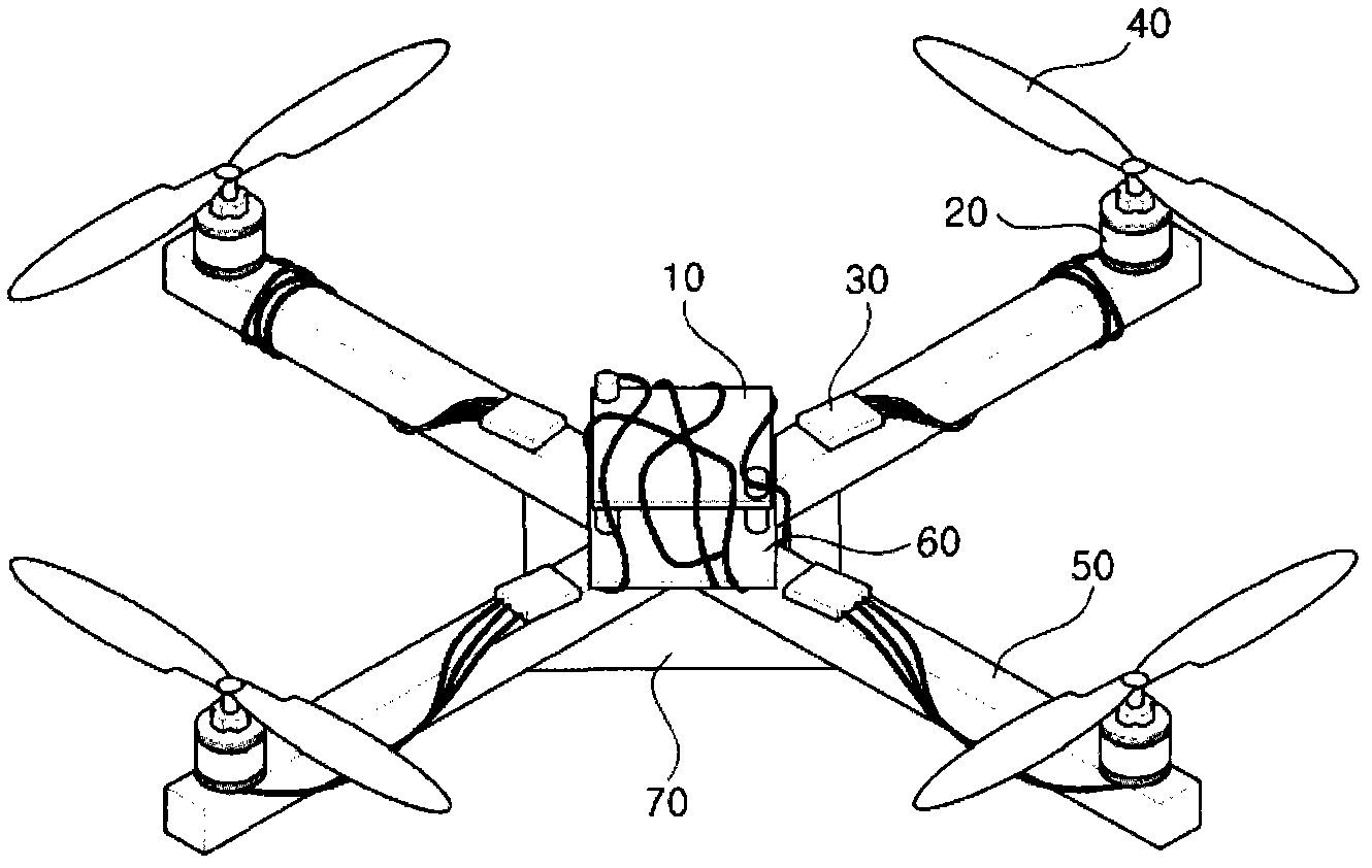
[0032] The "unmanned aerial vehicle" recorded throughout the instructions refers to an aircraft that can be controlled remotely even if no one directly pilots the aircraft. It specifically includes Tri-Rotor with 3 propellers, Quad-Rotor with 4 propellers, Penta-Rotor with 5 propellers, and Penta-Rotor with 6 propellers. Hexa-Rotor, Octo-Rotor with 8 propellers. Therefore, for the convenience of describing the present invention below, a quadrotor is used for illustration, but the protection scope of the present invention is not limited thereto. According to the number and structure of propellers, unmanned aerial vehicles of various shapes can be formed.

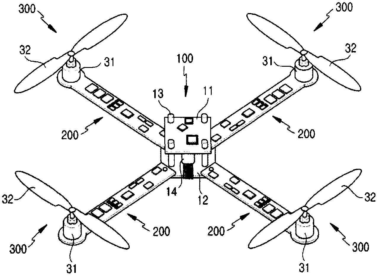
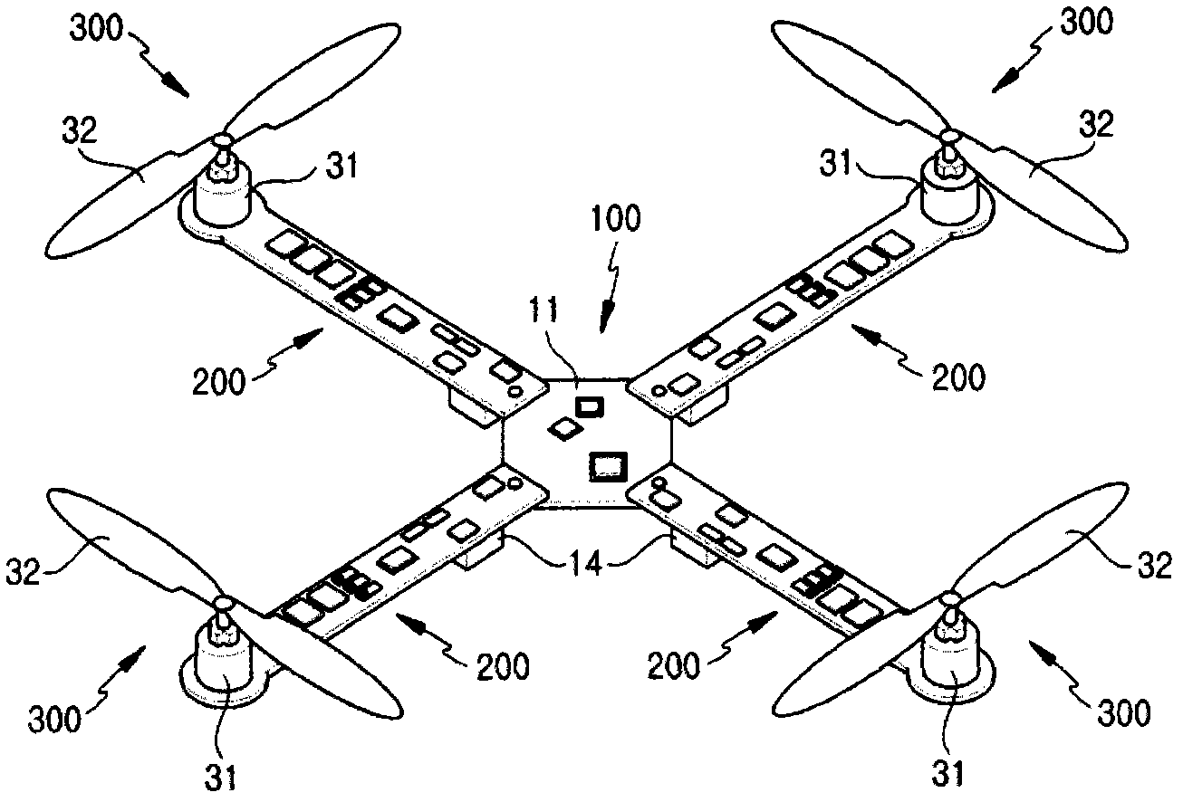
[0033] figure 2 The structure of an unmanned aerial vehicle related to an embodiment of the present invention is ...


PUM


Abstract

The present invention relates to an unmanned flying vehicle using a PCB including a main board controlling power supply and flying operation, a motor rotating a propeller by changing electric energy into mechanical energy, a PCB frame changing a signal from a remote controller and connecting the main board with the motor, a propeller generating an impellent force by from rotation by the motor, a receiver receiving a control signal of the remote controller, and a remote controller controlling a motor rotation speed of a quadrotor and direction change, and accordingly, the structure of the unmanned flying vehicle can be simplified so that the flying vehicle can be down-sized and light-weighted, and assemblability can be improved.

Description

technical field [0001] The present invention relates to an unmanned aerial vehicle, the structure of which is composed of a printed circuit board (hereinafter referred to as "PCB") for mounting electronic components, so that the unmanned aerial vehicle becomes miniaturized or lightweight, and reduces Cost of production. Background technique [0002] Recently, the demand for unmanned aerial vehicles has gradually increased in environments where operations are difficult. The application of unmanned aerial vehicles is also becoming more and more extensive, such as aerial image acquisition, power line detection in inaccessible disasters or disaster areas, or providing enemy hidden information on the battlefield or performing reconnaissance and surveillance tasks through unmanned aerial vehicles Wait. [0003] In the structure of the existing unmanned aerial vehicles, the body and the wings constituting the frame of the aircraft are composed of simple composite materials or woo...

Claims


Application Information

Patent Timeline
Patent Type & Authority Applications(China)
IPC IPC(8): B64C27/08B64C13/16
CPCB64C25/32B64C39/024B64U10/13B64U50/19B64U30/20
Inventor 李成镐李勇承
Owner DREAM SPACE WORLD CORP
Why Eureka
Try Eureka