Anaerobic reaction furnace for producing combustible gas

An anaerobic reaction and gas technology, applied in the field of anaerobic reactors, can solve the problems of high price, large air pollution, large floor space, etc., and achieve the effect of solving processing problems and simple structure

Inactive Publication Date: 2013-09-11
GUANGAN ANQI DAILY COMMODITIES
View PDF5 Cites 0 Cited by
  • Summary
  • Abstract
  • Description
  • Claims
  • Application Information

AI Technical Summary

Problems solved by technology

This treatment method is simple, but it occupies a large area and pollutes the surrounding environment very seriously, especially the non-degradable plastic waste in the garbage, which is particularly destructive to the environment.
2. First crush the garbage into fine materials with crushing equipment, so that the pulverized fine garbage can be fully burned, and then put it into the furnace for incineration, and in the process of burning garbage, it is necessary to assist fuel injection to support combustion. This method uses garbage direct combustion This is a better way of garbage disposal and utilization at present, but once this way of incineration of garbage to generate electricity is not well controlled, when the temperature is around 800 degrees during the garbage incineration process, a large amount of waste will be generated. Dioxins are discharged from chimneys, causing great pollution to the surrounding air. Therefore, many areas are concerned about the pollution caused by waste incineration power generation and are not accepted by people. Therefore, the use of waste incineration power generation technology cannot be promoted.
Moreover, this kind of equipment for incinerating waste and utilizing waste incineration to generate electricity is expensive, requires a lot of investment, and the cost of construction and use is very large, so it is not conducive to widespread promotion.

Method used


Image

  • Anaerobic reaction furnace for producing combustible gas
  • Anaerobic reaction furnace for producing combustible gas
  • Anaerobic reaction furnace for producing combustible gas

Examples


Embodiment Construction

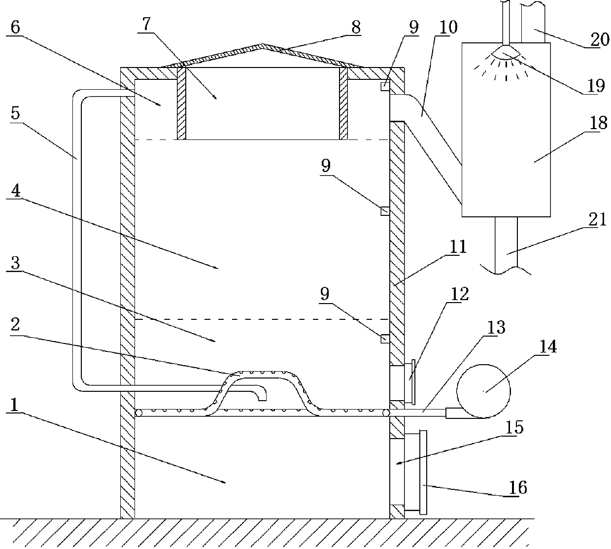
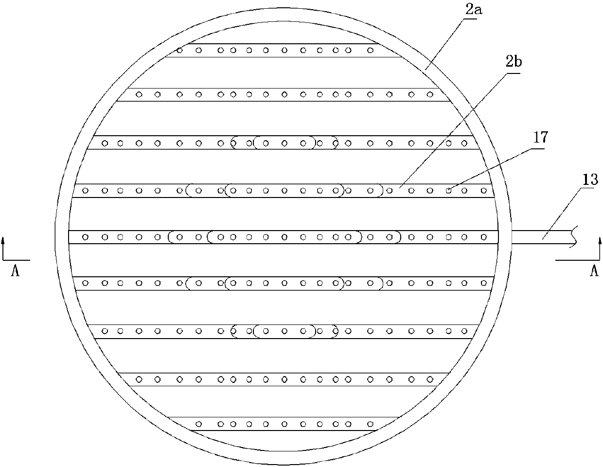
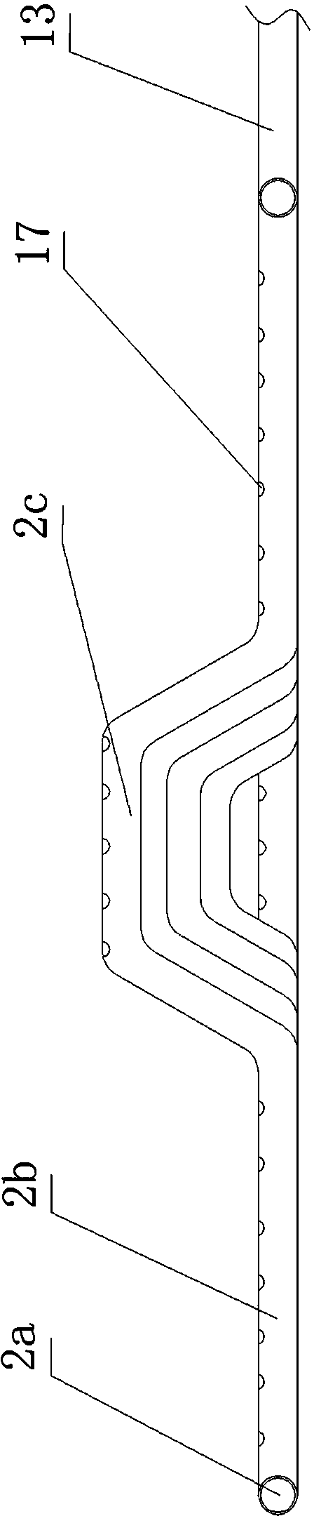
[0025] see Figures 1 to 2, an anaerobic reaction furnace for generating combustible gas, comprising a vertical furnace body 11, the interior of the furnace body 11 is divided into an upper chamber and a lower chamber by a furnace bridge 2, the upper part of the furnace bridge 2 is a reaction chamber, and the reaction chamber is from the upper Downwards include gas gathering chamber 6, drying zone 4, and anaerobic combustion reaction zone 3. 15 to 25% of the height of the reaction chamber is gas gathering chamber 6, and 20% of the height is the best. The volume of gas gathering chamber 6 The minimum, 45-55% of the height of the reaction chamber is the drying zone 4, and 50% is the best, the volume of the drying zone 4 is the largest, and 30% of the height of the reaction chamber is the anaerobic combustion reaction zone 3. Zone 3 is adjacent to the furnace bridge 2; below the furnace bridge 2 is the ash deposit chamber 1, the ash deposit chamber 1 is provided with a slag outle...


PUM


Abstract

The invention discloses an anaerobic reaction furnace for producing combustible gas. The anaerobic reaction furnace comprises a vertical furnace body, wherein the inside of the furnace body is partitioned into a reaction cavity above a flame bridge and a dust collecting cavity below the flame bridge by the arranged flame bridge; the reaction cavity comprises a gas collecting chamber, a drying region and an anaerobic combustion reaction region from top to bottom; the upper end of the furnace body is provided with a feeding hole; the feeding hole is covered with a sealing cover, and cylindrically extends into the reaction cavity; the gas collecting chamber is formed between the cylinder wall of the feeding hole and the side wall of the reaction cavity, and is connected with a purifier through an exhaust pipe; the flame bridge is an oxygen replenishing flame bridge made of hollow pipes; the hollow pipes of the flame bridge are provided with a plurality of oxygen replenishing holes facing the anaerobic combustion reaction region; the hollow pipes of the flame bridge are communicated with one another, and are communicated with an air blower positioned outside the furnace body through a blast pipe; the dust collecting cavity is provided with a slag outlet; and a furnace door is arranged at the slag outlet. Waste garbage is put into the furnace for undergoing an anaerobic combustion reaction to generate combustible gases, mainly carbon monoxide, so that combustible gases are provided for industrial production and family life, and environmental pollution is avoided.

Description

technical field [0001] The invention relates to a garbage treatment furnace, in particular to an anaerobic reaction furnace which uses garbage to generate combustible gas. Background technique [0002] The existing waste disposal has the following treatment methods: 1. Garbage filling treatment, which is the most widely used method at present. The collected mixed garbage will be piled up in the landfill, and after the garbage accumulation reaches a certain amount, it will be covered. soil for landfill. This treatment method is simple, but it occupies a large area and pollutes the surrounding environment very seriously, especially the non-degradable plastic waste in the garbage, which is particularly destructive to the environment. 2. First crush the garbage into fine materials with crushing equipment, so that the pulverized fine garbage can be fully burned, and then put it into the furnace for incineration, and in the process of burning garbage, auxiliary fuel injection is ...

Claims


Application Information

Patent Timeline
Patent Type & Authority Patents(China)
IPC IPC(8): C10J3/60C10J3/20C10J3/84C10J3/72
Inventor 庹小世
Owner GUANGAN ANQI DAILY COMMODITIES
Why Eureka
Try Eureka