Hydrostatic test device used for large-diameter thick-wall pipe joint and hydrostatic test method thereof

A hydraulic test and pipe joint technology, applied in the direction of applying stable tension/pressure to test the strength of materials, pipes/pipe joints/fittings, measuring devices, etc., can solve the problem of heavy welding workload, increased forging cost, high forging cost, etc. problems, to achieve the effects of shortened production cycle, reduced production cost, and mature manufacturing process

Inactive Publication Date: 2012-03-21
SHANGHAI BOILER WORKS
View PDF6 Cites 3 Cited by
  • Summary
  • Abstract
  • Description
  • Claims
  • Application Information

AI Technical Summary

Problems solved by technology

Large-diameter thick-walled pipe joints are usually manufactured by forging, and the forging cost is high. The longer the forging, the higher the forging cost and the difficulty
If the welding of this structure does not reach the weld height required by the design, it is very likely that the welding part of the pipe joint 2' will leak or the sealing plate 3 will fly out due to the huge pressure during the hydraulic test, causing serious casualties.
Therefore, the traditional large-diameter thick-wall pipe joint hydraulic test device has disadvantages such as large welding workload and high manufacturing cost.

Method used


Image

  • Hydrostatic test device used for large-diameter thick-wall pipe joint and hydrostatic test method thereof
  • Hydrostatic test device used for large-diameter thick-wall pipe joint and hydrostatic test method thereof
  • Hydrostatic test device used for large-diameter thick-wall pipe joint and hydrostatic test method thereof

Examples


Embodiment 1

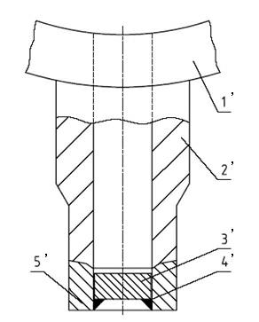
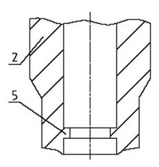
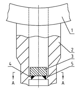
[0069] Such as figure 2 As shown, it is a structural cross-sectional view of a large-diameter thick-walled pipe joint 2. During forging, other structures of the large-diameter thick-walled pipe joint 2 are processed according to the design size, and only the inner diameter of the pipe joint 2 is kept close to the port. figure 2 As shown in bump 5, as Figure 4 As mentioned above, the protrusion 5 is processed into a circular truncated cone with a through hole in the middle and a certain thickness. When the sealing plate 3 is put into the pipe joint 2 through the pipeline body 1, the image 3 The sealing plate 3 and the protrusion 5 are welded at the position shown in , at this time, the weld seam 4 only acts as a seal, and the part of the protrusion 5 that is in contact with the sealing plate 3 bears the force exerted on the sealing plate 3 by the hydraulic test. Since the protrusion 5 is integrated with the pipe joint 2, it can bear a large force, which can prevent the se...

Embodiment 2

[0071] Such as Figure 5 As shown, it is a structural cross-sectional view of a large-diameter thick-walled pipe joint 2. During forging, other structures of the large-diameter thick-walled pipe joint 2 are processed according to the design size, and only the inner diameter of the pipe joint 2 is kept close to the port. Figure 5 For the protrusion 5 shown, when the sealing plate 3 cannot be put into the pipe joint 2 through the pipe body 1, the middle of the protrusion 5 is processed as Figure 6 Shown is a frustum of circular shape with a similar oval-shaped through-hole and a certain thickness. At this time, the shape of the sealing plate 3 which acts as a plug is similar to the shape of the through hole on the protrusion 5, which is similar to an ellipse. During hydrostatic testing, such as Figure 7 As shown, put the sealing plate 3 obliquely from the end of the pipe joint 2 port, and pass through the through hole on the protrusion 5 (such as Figure 8 shown), then rot...

Embodiment 3

[0073] Such as Figure 10 Shown, other steps are exactly the same as embodiment 2. When the direction of the pipe joint 2 is upward or other factors make it inconvenient for the sealing plate 3 to be in place, the auxiliary rod 6 can be connected to the sealing plate 3, and the sealing plate 3 can be moved from the end of the port of the pipe joint 2 by using the auxiliary rod 6. The plate 3 passes obliquely through the through hole on the protrusion 5, and then rotated 90° to be placed and then welded. After the hydrostatic test, the protrusion 5 is cut off, and the sealing plate 3 is separated from the pipe joint 2, and then the inner wall of the pipe joint 2 at the protrusion 5 is machined to the designed size. At the same time, the protrusion 5, the sealing plate 3, and the auxiliary rod 6 in place are separated, and the residual welding slag on the sealing plate 3 is removed. At this time, the sealing plate 3 and the auxiliary rod 6 in place can be reused.


PUM


Abstract

The invention discloses a hydrostatic test device used for a large-diameter thick-wall pipe joint and a hydrostatic test method thereof. When the large-diameter thick-wall pipe joint is forged, a pipe joint bulge part is forged at the inner diameter of the pipe joint; a closing plate is welded on the bulge part; a gap between the bulge and the closing plate is subjected to seal welding; because the bulge and the pipe joint are integral, big action force can be borne so as to prevent the closing plate from flying out because of overlarge pressure; at the time, a welding line only play the effect of sealing, and welding height is far smaller than the welding height in the traditional hydrostatic test device, thereby greatly lowering welding cost; then, the hydrostatic test is carried out; after the hydrostatic test is finished, the bulge is cut off; and then, the inner wall of the pipe joint at the position where the bulge is arranged is machined to a designed size. Therefore, the hydrostatic test is safely finished, material is saved, the forging cost of the pipe joint is lowered, the welding cost of the closing plate is lowered, the preparation period of the hydrostatic test is shortened, and production cost is lowered.

Description

technical field [0001] The invention relates to a hydraulic test device and a hydraulic test method for large-diameter thick-walled pipe joints. Background technique [0002] Hydrostatic testing is one of the essential technologies for checking product quality in the manufacturing process of industrial pipelines. Taking power plant boilers as an example, steam drums, headers, desuperheaters and other similar boiler components must be hydrostatically tested when they are manufactured. Pressure test to check whether its material and welding joint pressure requirements meet the design requirements and the relevant national regulations on pressure vessel acceptance. [0003] The boiler components produced in the manufacturing plant are often welded with large-diameter thick-walled pipe joints, which must be blocked during the hydraulic test. figure 1 It is a traditional hydraulic test device. When manufacturing the pipe joint 2', the pipe end is first manufactured to have a ce...

Claims


Application Information

Patent Timeline
Patent Type & Authority Applications(China)
IPC IPC(8): G01N3/12
CPCF16L23/167G01L19/0007G01N3/12G01M3/2853G01M3/022
Inventor 王瑞娟周曙光叶伟民赵朋山
Owner SHANGHAI BOILER WORKS
Why Eureka
Try Eureka