Stage apparatus, lithographic apparatus and method of positioning an object table

An object and platform technology, applied in the field of positioning object platform, can solve problems such as deformation, grid plate affecting movement or deformation, negative measurement system accuracy, etc.

Active Publication Date: 2012-03-21
ASML NETHERLANDS BV
View PDF5 Cites 12 Cited by
  • Summary
  • Abstract
  • Description
  • Claims
  • Application Information

AI Technical Summary

Problems solved by technology

[0009] A disadvantage of the known measuring system is that the grid plate can be shifted or deformed by external influences because the mounting device of the grid plate, especially the flexible element, introduces some flexibility in the mounting of the grid plate
For example, movement of the substrate pla

Method used


Image

  • Stage apparatus, lithographic apparatus and method of positioning an object table
  • Stage apparatus, lithographic apparatus and method of positioning an object table
  • Stage apparatus, lithographic apparatus and method of positioning an object table

Examples


Embodiment Construction

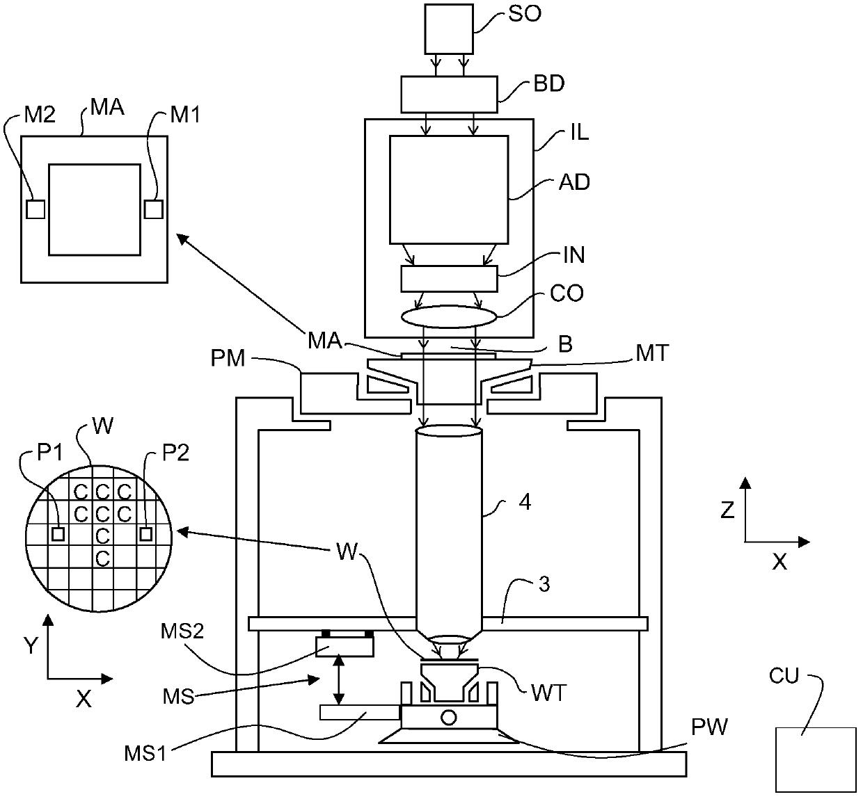
[0024] figure 1 A lithographic apparatus according to an embodiment of the present invention is schematically shown. The apparatus includes: an illumination system (illuminator) IL configured to condition a radiation beam B (e.g., ultraviolet (UV) radiation or any other suitable radiation); a patterning device support or support structure (e.g., a mask table ) MT configured to support a patterning device (eg mask) MA and connected to a first positioning device PM configured to precisely position the patterning device according to determined parameters. The apparatus also includes a substrate table (e.g., wafer table) WT or "substrate support" configured to hold a substrate (e.g., resist-coated wafer) W and is connected to a second positioning device PW configured to precisely position the substrate according to determined parameters. The apparatus further comprises a projection system or lens column (e.g. a refractive projection lens system, for example comprising a lens col...


PUM


Abstract

The invention discloses a stage apparatus, a lithographic apparatus and a method of positioning an object table. The stage apparatus comprises a measurement system configured to measure a position dependent signal of an object table, the measurement system including at least one sensor mountable on the object table and a sensor target object mountable on a substantially stationary frame, and a mounting device configured to mount the sensor target object on the substantially stationary frame, wherein the measurement system further includes a compensator configured to compensate movements and/or deformations of the sensor target object with respect to the substantially stationary frame. The compensator may include a passive or an active damper and/or a feedback position controller. In an alternative embodiment, the compensator includes a gripping device which fixes the position of the sensor target object during a high accuracy movement of the movable object.

Description

technical field [0001] The invention relates to a platform device, a lithographic device and a method of positioning an object stage. Background technique [0002] A lithographic apparatus is a machine that applies a desired pattern to a substrate, usually to a target portion of the substrate. For example, lithographic equipment may be used in the manufacture of integrated circuits (ICs). In this case, a patterning device, alternatively referred to as a mask or reticle, may be used to generate the circuit pattern to be formed on the individual layers of the IC. The pattern can be transferred onto a target portion (eg, comprising a portion, one or more dies) on a substrate (eg, a silicon wafer). Typically, the pattern is transferred via imaging to a layer of radiation sensitive material (resist) provided on the substrate. Typically, a single substrate will contain a network of successively patterned adjacent target portions. A conventional lithographic apparatus consists ...

Claims


Application Information

Patent Timeline
IPC IPC(8): G03F7/20
CPCG03F7/70775G03F7/7085G03F7/70716H01L21/0274G03F7/70725
Inventor 恩格尔伯塔斯·安东尼纳斯·弗朗西丝克斯·范德帕斯奇艾米尔·尤泽夫·梅勒妮·尤森A·B·杰尤恩克罗伯特·艾德加·范莱文
Owner ASML NETHERLANDS BV
Why Eureka
Try Eureka