L frequency band LTCC band pass filter

A technology of band-pass filter and frequency band, which is applied in the field of L-band LTCC band-pass filter to achieve the effect of reducing parameter sensitivity, improving yield and reducing the requirements of processing technology.

Active Publication Date: 2012-03-28
XIAN INSTITUE OF SPACE RADIO TECH
View PDF2 Cites 9 Cited by
  • Summary
  • Abstract
  • Description
  • Claims
  • Application Information

AI Technical Summary

Problems solved by technology

[0003] At present, there is no public literature reporting this technology at home and abroad.

Method used


Image

  • L frequency band LTCC band pass filter
  • L frequency band LTCC band pass filter
  • L frequency band LTCC band pass filter

Examples


Embodiment Construction

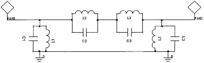
[0016] Such as figure 1 As shown, the present invention is a third-order bandpass filter with a pair of transmission zeros, including two LC parallel resonators connected in parallel to the ground, and two series-connected LC parallel resonators separately control a transmission zero, which is used in the design process This feature can improve work efficiency.

[0017] The input terminals of the filter are connected to the input terminals of the capacitors C1 and C2 and the inductors L1 and L2, the output terminals of C1 and L1 are grounded, the output terminals of C2 and L2 are connected to the input terminals of C3 and L3, and the output terminals of C3 and L3 are connected to the other The input terminals of a pair of C1 and L1 are connected with the output terminals of the filter. Due to the parallel loop on the series branch, the transmission admittance of the whole circuit is 0 at parallel resonance, so the two loops form two independently controllable transmission zer...


PUM


Abstract

An L frequency band LTCC band pass filter comprises five layers of medium substrates and six layers of metal layers. A bottom layer is a grounding metal layer. A top layer is an input output layer. Over-travel high impedance strip lines of the second and the third layers form an inductor L2 and an inductor L3 which are connected to the input output layer of the first layer through metal through holes of the third layer. Metal discs of a fourth layer and a fifth layer form a capacitor C2 and a capacitor C3. And the capacitor C2 and the capacitor C3 are connected to the inductors of the second and the third layers through the metal through holes of the second layer so as to form a series connection relation. The metal disc of the fifth layer and the grounding metal layer form a capacitor C1. Simultaneously, two stages of high impedance lines of the fourth and the fifth layers are connected with each other through the metal through holes so as to form an inductor L1 and are connected to ground so as to form a grounded inductor. By using the filter, parameter sensitivity of the filter can be reduced; a requirement to a processing technology can be reduced and a finished products rate can be effectively increased.

Description

technical field [0001] The invention relates to a band-pass filter, in particular to an L-band LTCC (low temperature co-fired ceramic) band-pass filter. Background technique [0002] Microwave bandpass filter is a key component of microwave radio system. With the development of microwave circuit design simulation technology and process in recent years, the demand for miniaturization of radio frequency system is getting higher and higher, and the miniaturization of filter is even more important. Bearing the brunt, how to reduce the size of the filter as much as possible while ensuring a certain performance index has become an important problem to be solved in the miniaturized radio frequency system. LTCC technology is a multi-layer ceramic technology developed in recent years. Using this technology, three-dimensional structures that cannot be realized by traditional ceramic substrate technology can be realized. Designing microwave passive devices using LTCC technology has gr...

Claims


Application Information

Patent Timeline
Patent Type & Authority Applications(China)
IPC IPC(8): H01P1/20H03H7/01
Inventor 杨毅民姜立伟韩红波梁军利
Owner XIAN INSTITUE OF SPACE RADIO TECH
Why Eureka
Try Eureka