
Variable-frequency electromagnetic heating device

A heating and electromagnetic technology, applied in the field of heating, can solve the problems of affecting the system work, reducing the efficiency of heat energy utilization, and inconvenient maintenance, etc., and achieve the effects of safe and reliable system, enhanced service life, and structural safety

Inactive Publication Date: 2012-04-04
宁波高新区安立特电气科技有限公司
View PDF6 Cites 3 Cited by
  • Summary
  • Abstract
  • Description
  • Claims
  • Application Information

AI Technical Summary

Problems solved by technology

But there are following disadvantages: one: the resistance wire (or metal wire) is directly put into the water, and the time is permanent, and it is inevitable that the surface of the resistance wire (or metal wire) will not be rusted, causing electric leakage, and there is a potential safety hazard. Moreover, the resistance wire (or metal wire) is easily damaged in a humid environment, which greatly shortens the life of the heater; second: the resistance wire (or metal wire) needs to consume a lot of energy for heating
The gas heater uses burning gas as a heating element. The cost of gas is high, the structure is relatively complicated, and although the service life is long, because the gas wastes more heat energy during use, the utilization efficiency of the heat energy is reduced, which further causes gas heating. waste, and there are many electromagnetic induction heaters on the market. Although they start to save energy, most of them are not easy to maintain and affect the system work.

Method used


Image

  • Variable-frequency electromagnetic heating device
  • Variable-frequency electromagnetic heating device
  • Variable-frequency electromagnetic heating device

Examples


Embodiment

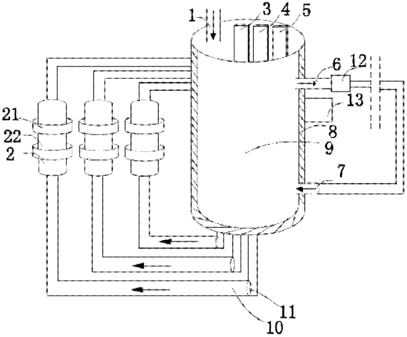
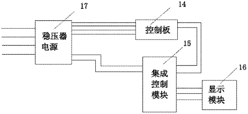
[0015] Such as figure 1 , figure 2 As shown, the frequency conversion electromagnetic heater provided by the present invention includes a hot water tank 9 and a heating fin 12, and the upper end of the hot water tank 9 is provided with a water inlet pipe 1, a water level detector 3, a pressure detector 4 and a temperature detector 5. One end of the water tank 9 is provided with a water return pipe 7 and a hot water outlet pipe 6, the hot water outlet pipe 6 is connected to the heating fin 12, and a heating device 2 for circulating water heating is connected outside the hot water tank 9 through a guide pipe 10, The heating device 2 includes a metal tube 22 and an electromagnetic induction heating coil 21, the electromagnetic induction heating coil 21 is sleeved on the outer surface of the metal tube 22, a diversion pump 11 is arranged in the diversion tube 10, and the hot water tank 9 is fixed There is a control circuit 13 for controlling the circulating water through the wat...


PUM


Abstract

The invention discloses a variable-frequency electromagnetic heating device. The variable-frequency electromagnetic heating device comprises a hot water tank and a heating piece, and is characterized in that: a water inlet pipe, a water level detector, a pressure detector and a temperature detector are arranged at the upper end of the hot water tank; a water return pipe and a hot outlet pipe are arranged at the end on one side of the hot water tank; a hot water outlet pipe is connected with the heating piece; a heating device used for heating circulating water is connected out of the hot water tank through a diversion pipe; the heating device comprises a metal pipe and an electromagnetic induction heating coil; the electromagnetic induction heating coil is sleeved on the outer surface of the metal pipe; a diversion pump is arranged in the diversion pipe; and a control circuit for controlling the circulating water through the water level detector, the pressure detector, the temperature detector, the electromagnetic induction heating coil and the diversion pump is fixed to the hot water tank. The variable-frequency electromagnetic heating device performs circulation external heating on water, is safer in structure, reduces cost, prolongs service life, and achieves an energy-saving effect; and when a group of electromagnetic induction coils fail, other coils cannot be influenced, so that the system can be used normally and is convenient to use.

Description

technical field [0001] The invention relates to a heater, in particular to a variable frequency electromagnetic heater. Background technique [0002] Existing heater kind is a lot, as: electric heater, gas heater etc. Electric heaters currently on the market generally use resistance wires (or metal wires) as heating elements, and put them in direct contact with water. By energizing the resistance wires (or metal wires), they generate current, and the electric energy is generated by the resistance wires (or metal wires). or wire) into Joule heat, which heats the water. But there are following disadvantages: one: the resistance wire (or metal wire) is directly put into the water, and the time is permanent, and it is inevitable that the surface of the resistance wire (or metal wire) will not be rusted, causing electric leakage, and there is a potential safety hazard. And resistance wire (or metal wire) is very easily damaged in humid environment, makes the life-span of heater...

Claims


Application Information

Patent Timeline
IPC IPC(8): F24D13/04F24D19/10
Inventor 丁长志
Owner 宁波高新区安立特电气科技有限公司
Learn More