
High-power sound wave transmitting device for depth measuring instrument

A sound wave emission and sounder technology, applied in the direction of measuring devices, sound wave re-radiation, instruments, etc., can solve the problems of circuit damage, difficult transmission of the signal top, easy distortion of the emission waveform, etc., and achieve the effect of stable operation.

Active Publication Date: 2012-04-04
WUXI HAIYING CAL TEC MARINE TECH
View PDF1 Cites 4 Cited by
  • Summary
  • Abstract
  • Description
  • Claims
  • Application Information

AI Technical Summary

Problems solved by technology

However, it usually has the following defects: First, because the step-up transformer needs to realize the electric-magnetic and magnetic-electric conversion successively, the maximum transmission width of the signal is limited by the magnetic saturation characteristic, so the top of the signal is not easy to transmit, and the transmitted waveform is easy to be distorted; Secondly, the minimum width of the signal is limited by the magnetizing current; thirdly, when using a low-frequency emission sound wave (such as 10kHz), in order to achieve high-power emission, it is necessary to select a transformer with a relatively large boost voltage, and to suppress the magnetic saturation characteristic, The transformer must be bulky, heavy, and complicated to process. Even so, the transmission power can only reach about 2000W, which is still not ideal; finally, the transmission protection circuit of the traditional depth sounder collects the power of the main circuit through the sampling resistor on the ground side The current data is sent to the control circuit of the depth sounder in an analog manner. When the circuit has an abnormal situation such as a short circuit, the control signal is output, and all transmissions are turned off to protect the transmission circuit. Due to the consideration of the common ground of the circuit, the existence of the sampling resistor may cause circuit damage. The response of the protection circuit is not fast enough

Method used


Image

  • High-power sound wave transmitting device for depth measuring instrument
  • High-power sound wave transmitting device for depth measuring instrument
  • High-power sound wave transmitting device for depth measuring instrument

Examples


Embodiment Construction

[0041] Below in conjunction with accompanying drawing and example, the present invention will be further described:

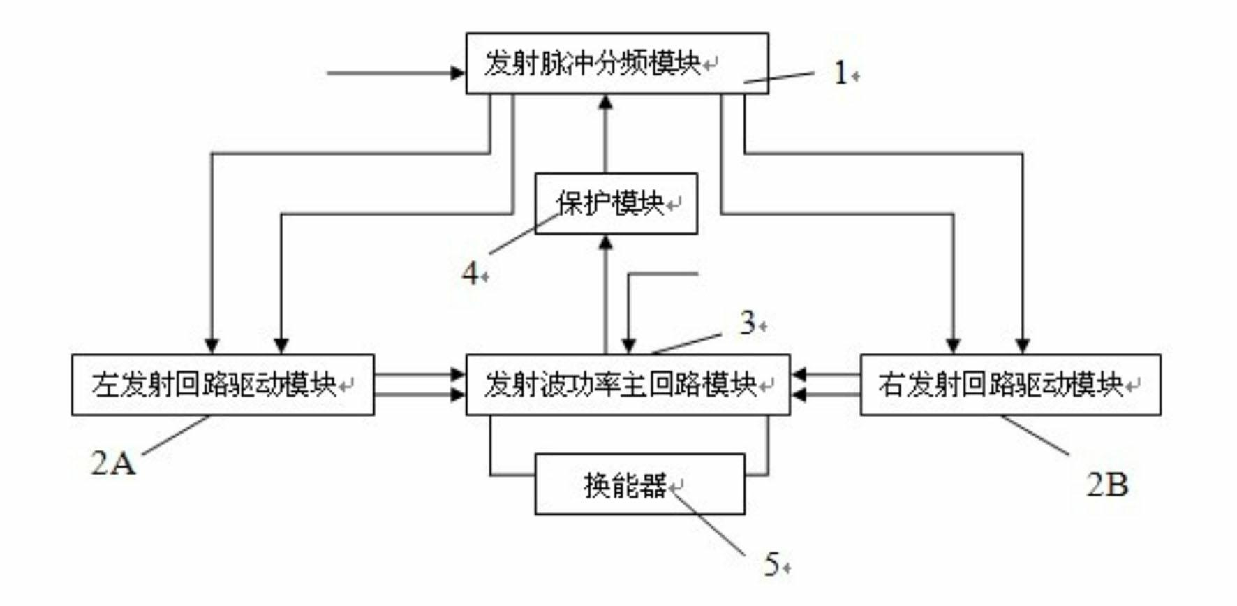
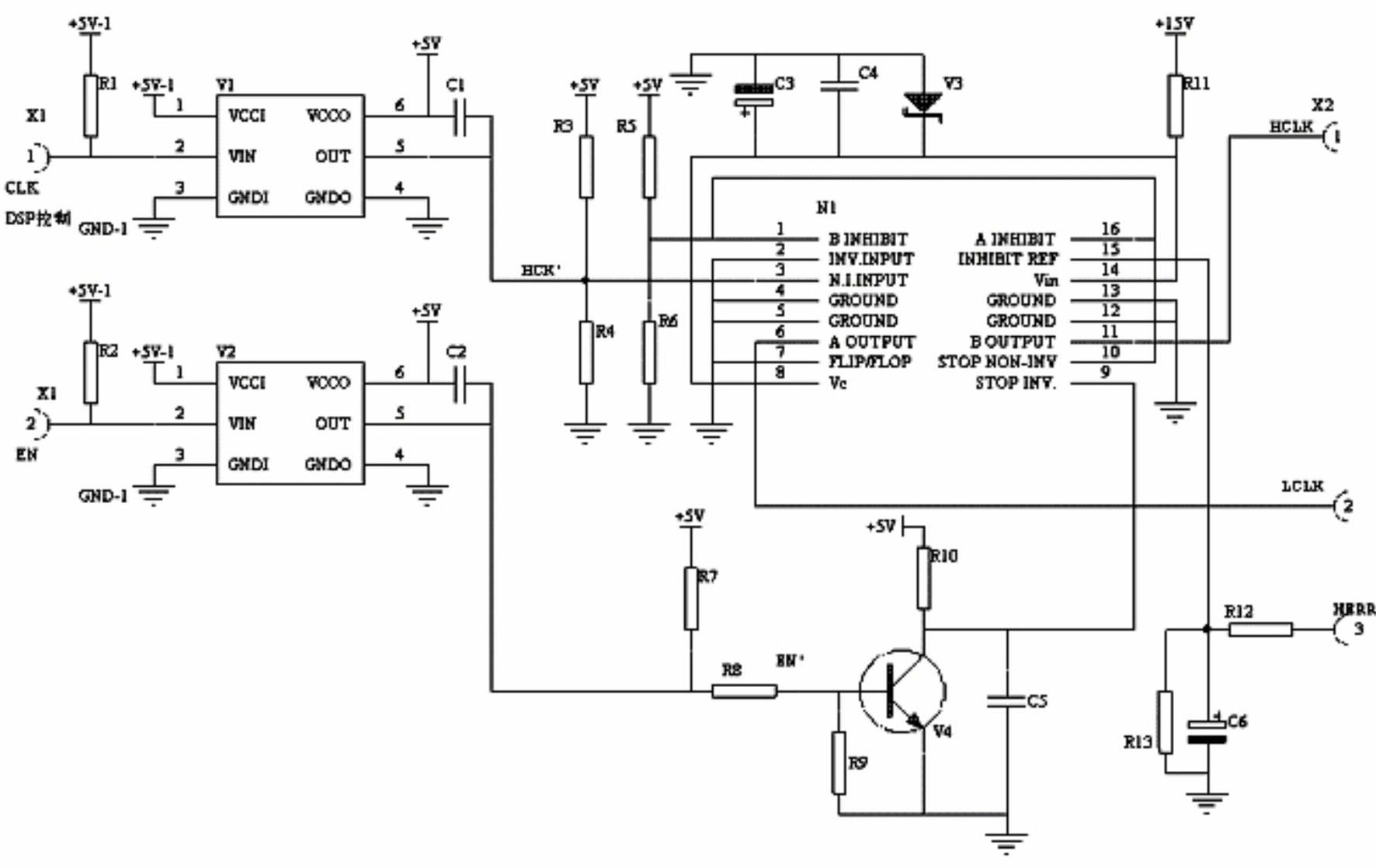
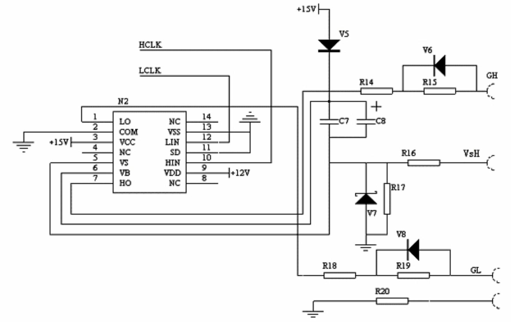
[0042] like figure 1 As shown in the figure, the sounder sound wave transmitting device mainly includes: a transmitting pulse frequency dividing module 1, a transmitting circuit driving module 2, a transmitting wave power main circuit module 3 and a transducer 5; wherein, the transmitting pulse frequency dividing module 1 is connected to the transmitting pulse frequency dividing module 1. The loop driving module 2, the transmitting loop driving module 2 and the transducer 5 are respectively connected to the transmitting wave power main loop module 3.

[0043] The transmit pulse frequency division module 1 is used to receive the transmit pulse signal sent by the echo sounder control circuit, and send the positive half-cycle and negative half-cycle transmit wave pulse signals respectively formed after the two-frequency division to the transmit loop drive module 2...


PUM


Abstract

The invention relates to a sound wave transmitting device for depth measuring instrument, which belongs to the technical field of sonar measurement equipment for underwater survey using sound wave, and particularly relates to a high-power sound wave transmitting device for depth measuring instrument. The device mainly comprises a transmission pulse frequency dividing frequency, a transmission loop drive module, a transmission wave power main loop module, a protection module and an energy converter, wherein the transmission pulse frequency dividing module receives a transmission pulse signal from a depth measuring instrument control circuit, and transmits transmission pulse signals of positive and negative half cycles of transmission wave formed respectively after frequency division to left and right transmission loop drive modules; the left and right transmission loop drive modules drive each switch tube of full bridge circuit of the transmission wave power main loop module; the transmission wave power main loop module loads high voltage direct current to the energy converter through the full bridge circuit formed by four switch tubes to form transmission sound wave of the depth measuring instrument; and the protection module acquires a signal from the power main loop module, and a control signal is output when the circuit has exceptional situation such as short circuit and the like to stop all the transmissions so as to protect transmission circuits. Quality of sound wave transmission of the depth measuring instrument can be greatly improved by such high-power transmission circuit without transformer, and the device has wide application prospect.

Description

[0001] technical field [0002] The invention relates to a sound wave emission device for a depth sounder, in particular to a high-power sound wave emission device dedicated to a depth sounder, and belongs to the technical field of sonar measurement equipment for underwater measurement using sound waves. [0003] Background technique [0004] As the most effective means of underwater detection, underwater acoustic signals have been widely used in various sonar devices for underwater target detection. The echo sounder is a conventional water depth measurement equipment that uses underwater acoustic signals for distance measurement, and it is also the most commonly used detection equipment today. Its working principle is to transmit sound waves of a certain frequency through the transducer. When sound waves propagate in water, they will generate reflection signals when encountering media with different densities (such as the bottom of the water or other objects). The propaga...

Claims


Application Information

Patent Timeline
Patent Type & Authority Applications(China)
IPC IPC(8): G01S7/524G01S15/08
CPCY02A90/30
Inventor 陈钧
Owner WUXI HAIYING CAL TEC MARINE TECH
Learn More