Servo control system

A servo control system and programming control technology, applied in the field of servo control systems, can solve problems such as equipment lag, reduced processing efficiency, and complicated wiring, and achieve the effects of reducing failure rates, improving processing efficiency, and saving costs

Inactive Publication Date: 2012-04-04
CHENGDU VISTA CNC MFR
View PDF4 Cites 10 Cited by
  • Summary
  • Abstract
  • Description
  • Claims
  • Application Information

AI Technical Summary

Problems solved by technology

[0004] 1) The pulse signal is easily disturbed during the transmission process, especially when the transmission line is long, the inverter line, mobile phone signal and other signal lines are easy to cause the pulse signal to generate peak interference pulses, and the driver will reduce the interference pulse processed as a valid pulse signal such as Image 6 As shown, the driver will take the interference pulse 1 as an effective pulse, and the interference pulse 2 will divide the normal pulse signal into two pulses, which will directly cause positioning errors;
[0005] 2) The pulse signal sent by the positioning module of the programmable controller will be processed by the servo driver and then transmitted to the servo motor. The pulse signal transmission and processing time will be reflected in the rotation of the servo motor, causing the equipment to lag behind;
[0006] 3) Because all servo drivers have a limit value for the frequency of the pulse signal, when the frequency of the pulse signal is too high, the servo driver will not be able to recognize the pulse signal, so the movement speed of the equipment will be limited and the processing efficiency will be reduced;
[0007] 4) When the frequency of the pulse signal is high but below the limit value of the servo drive, it is easy for individual pulse servo drives to fail to recognize, resulting in pulse loss and inaccurate positioning;
[0008] 5) The wiring is complex, in addition to the pulse signal line, many control lines are required, and the line failure rate is high;
[0009] 6) The scalability is poor. When the CNC axis needs to be added, the hardware configuration must be changed

Method used


Image

  • Servo control system
  • Servo control system
  • Servo control system

Examples


Embodiment Construction

[0026] All features disclosed in this specification, or steps in all methods or processes disclosed, may be combined in any manner, except for mutually exclusive features and / or steps.

[0027] Any feature disclosed in this specification (including any appended claims, abstract and drawings), unless expressly stated otherwise, may be replaced by alternative features which are equivalent or serve a similar purpose. That is, unless expressly stated otherwise, each feature is one example only of a series of equivalent or similar features.

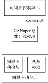
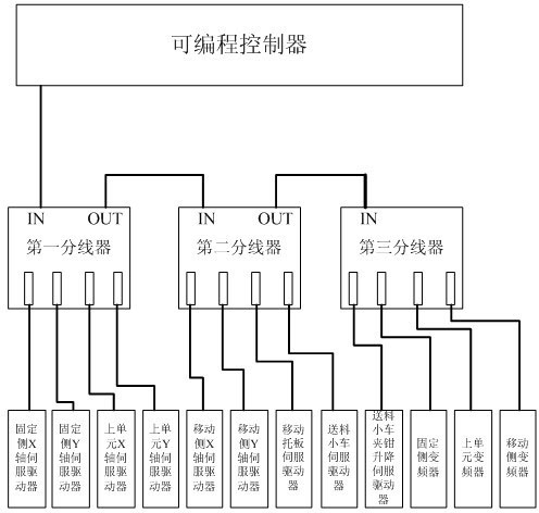
[0028] Such as figure 1 with figure 2 As shown, a servo control system of the present invention is used for precision numerical control processing equipment. In the embodiment of the present invention, the present invention is described in detail with a servo control system for a three-dimensional drilling machine tool for steel structures.

[0029] A servo control system includes a programmable control unit with a CANopen communication i...


PUM


Abstract

The invention discloses a servo control system applied to precise numerical-control machine tool processing equipment. The servo control system comprises a programmable control unit with a CAN (controller area network) open communication interface and a servo driving unit with a CAN open communication interface, and the programmable control unit is in communication with the servo driving unit via a CAN open bus. A positioning module of a programmable controller is omitted, the CAN open bus replaces a pulse signal wire and a control wire, consumption of wires is reduced by two-third, cost is saved, and simultaneously, failure rate of circuits is greatly reduced. Digital signals transmitted by the CAN open bus replace pulse signals of the prior art, problems that speed is limited due to over high pulse frequency and individual pulse signals cannot be identified by servo drivers in the prior art are resolved, the speed can be 1.5 times faster than the original speed, processing efficiency is improved, and precision is increased to 0.3mm from 0.5mm of the original precision.

Description

technical field [0001] The invention relates to a servo control system, in particular to a servo control system for precision numerical control processing equipment using CANopen bus communication. Background technique [0002] With the progress and development of the country, the steel structure industry has received more and more attention. At the same time, the equipment required for steel structure production has also developed rapidly. There are more and more types of machine tools used for steel structures, especially plane drilling. Equipment and 3D drilling equipment are the most popular. In steel structures used in some industries, such as the drilling of H-beams used in bridges and automobile balance shafts, the requirements for the position accuracy of the holes are quite high, and the requirements for processing efficiency are getting higher and higher. The control mode of the servo control system commonly used in the drilling equipment of the prior art is to se...

Claims


Application Information

Patent Timeline
Patent Type & Authority Applications(China)
IPC IPC(8): G05B19/414
Inventor 毕建波吴绍海
Owner CHENGDU VISTA CNC MFR
Why Eureka
Try Eureka