Transformer and winding method of transformer

A winding method and transformer technology, which are applied in the directions of transformer/inductor coil/winding/connection, coil manufacturing, printed circuit connected with non-printed electrical components, etc., can solve problems such as excessive change in cross adjustment rate

Inactive Publication Date: 2012-04-04
ANHUI TATFOOK TECH CO LTD
View PDF6 Cites 10 Cited by
  • Summary
  • Abstract
  • Description
  • Claims
  • Application Information

AI Technical Summary

Problems solved by technology

[0006] In order to solve the problem of excessive variation of the cross-regulation rate in the prior art, the embodiment of the present invention provides a transformer and a transformer winding method

Method used


Image

  • Transformer and winding method of transformer
  • Transformer and winding method of transformer
  • Transformer and winding method of transformer

Examples


Embodiment 1

[0026] In order to overcome the technical prejudice in the prior art that traditional transformers cannot realize fractional turns, the following examples illustrate that traditional transformers can realize fractional turns.

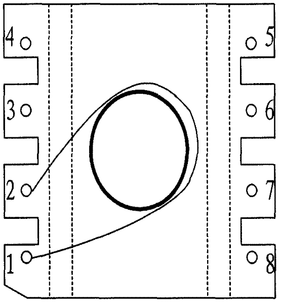
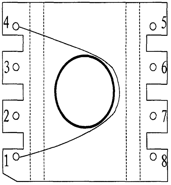
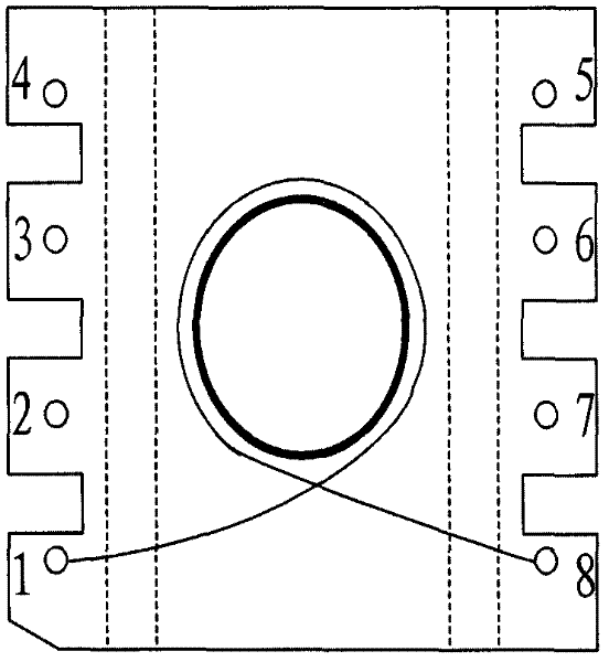
[0027] Such as Figure 1 to Figure 4 For the four winding situations shown, we basically treat them as one turn or one turn in the design process of magnetic components; but in a strict mathematical and physical sense, they are different.

[0028] We do not consider the difference in the distance between the skeleton pins, the difference in the winding process, and do not consider the coupling of fractional turns. suppose figure 1 The arc of every two adjacent pins of pins 1, 2, 3 and 4 corresponding to the center column of the magnetic core is 40°; every two adjacent pins of pins 5, 6, 7 and 8 correspond to the arc of the core column The arc is 40°; the arc of pin 1 and pin 8 is 60°; the arc of pin 1 and pin 5 is 180°.

[0029] Such as figure 1 As ...

Embodiment 2

[0034] A transformer winding method,

[0035] Determine the theoretical turns ratio of the secondary coil according to the required multi-channel output voltage ratio;

[0036] The integer number of turns of the secondary coil is determined according to the theoretical turns ratio of the secondary coil, and the integer number of turns is the number of coil turns wound around the transformer skeleton for one turn;

[0037] Adjust the number of turns of the fractional turns of the secondary coil so that the voltage value output by the multi-channel secondary coil is close to the required multi-channel output voltage value, and the fractional turns are based on any two different pins on the transformer as the starting point and The end point is not less than the number of turns wound around the transformer bobbin.

[0038] The step of adjusting the number of fractional turns of the secondary coil further includes: connecting the coil to different output terminals and changing th...

Embodiment 3

[0054] The present invention also proposes a transformer, which includes an integrated circuit board and a magnetic core passing through the hole in the integrated circuit board. Coil, the winding coil includes integer turns and fractional turns, the integer turns are the number of coil turns wound around the transformer skeleton, and the fractional turns are the starting and ending points of any two different pins on the transformer and winding the transformer The number of turns in which the bobbin is less than one turn.

[0055] The winding coil changes the number of fractional turns by connecting different output terminals.

[0056] When the skeleton of the transformer is a circular skeleton, the number of fractional turns is determined according to the position of the pins and the radian of the pins corresponding to the middle column of the magnetic core.

[0057] The radian of the middle column of the magnetic core corresponding to the two pins is a, and the number of t...


PUM


Abstract

The invention provides a transformer and a winding method of transformer. The theoretical turns ratio of the secondary coil is determined according to the multi-path rated output voltages and the integer number of turns of the secondary coil is determined according to the theoretical turns ratio of the secondary coil, wherein the integer number of turns is the turn ratio of one circle of the transformer skeleton; the number of decimal turns of the secondary coil is adjusted so that the voltage value outputted by each path of the multi-path secondary coils is close to the rated output voltage value; said decimal turns ratio is the number of turns by taking any two different pins as the starting point and the terminal point and winding the transformer skeleton for not more than one circle. The embodiment of the invention provides a designing method of the decimal turns of the transformer to obviously improve the cross adjusting rate of the multi-path output switch powers. The winding process is used via a lead-out pin of the transformer so as to obtain the needed decimal turns. The decimal turns can realize the precise turns ratio and adjust the outputted secondary leakage inductance.

Description

technical field [0001] The invention relates to a transformer and a transformer winding method. Background technique [0002] In the existing design, it is often necessary to develop a multi-output switching power supply to meet the needs of different power supply voltages required by different components and different circuits in the same active product. In the field of numerical control and communication, the accuracy of the power supply voltage is very high. Even when the load changes in a large range, the output voltage must be guaranteed within a certain range. In the multi-output switching power supply, only one of the outputs is selected as the main output, and the selection of the main output is based on the importance of each output, the requirements for voltage regulation accuracy, load current size and stability and other factors. After the main channel is selected, the other outputs are auxiliary channel outputs. Since the output of the main circuit is controll...

Claims


Application Information

Patent Timeline
Patent Type & Authority Applications(China)
IPC IPC(8): H01F41/06H01F27/28H05K1/18H01F41/08
Inventor 邱宜忠
Owner ANHUI TATFOOK TECH CO LTD
Why Eureka
Try Eureka