Light-emitting diode dehydrator

A diode and dehydrator technology, applied in dryers, non-progressive dryers, drying solid materials, etc., can solve the problems of poor effect and incomplete dehydration, and achieve the effect of preventing oxidation and convenient operation

Active Publication Date: 2012-04-11
RUGAO DACHANG ELECTRONICS
View PDF8 Cites 5 Cited by
  • Summary
  • Abstract
  • Description
  • Claims
  • Application Information

AI Technical Summary

Problems solved by technology

[0002] In the production process of diodes, pickled diodes need to be washed to remove residual acid, and dehydrated af

Method used


Image

  • Light-emitting diode dehydrator
  • Light-emitting diode dehydrator
  • Light-emitting diode dehydrator

Examples


Embodiment Construction

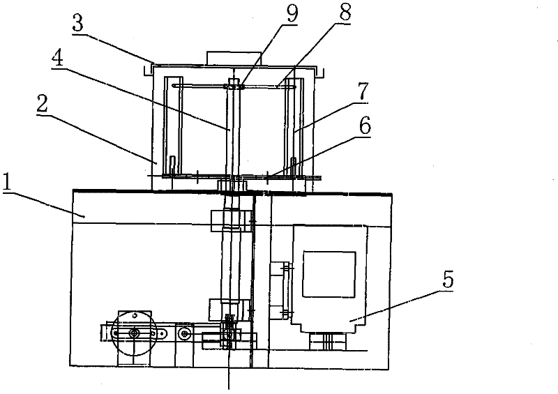
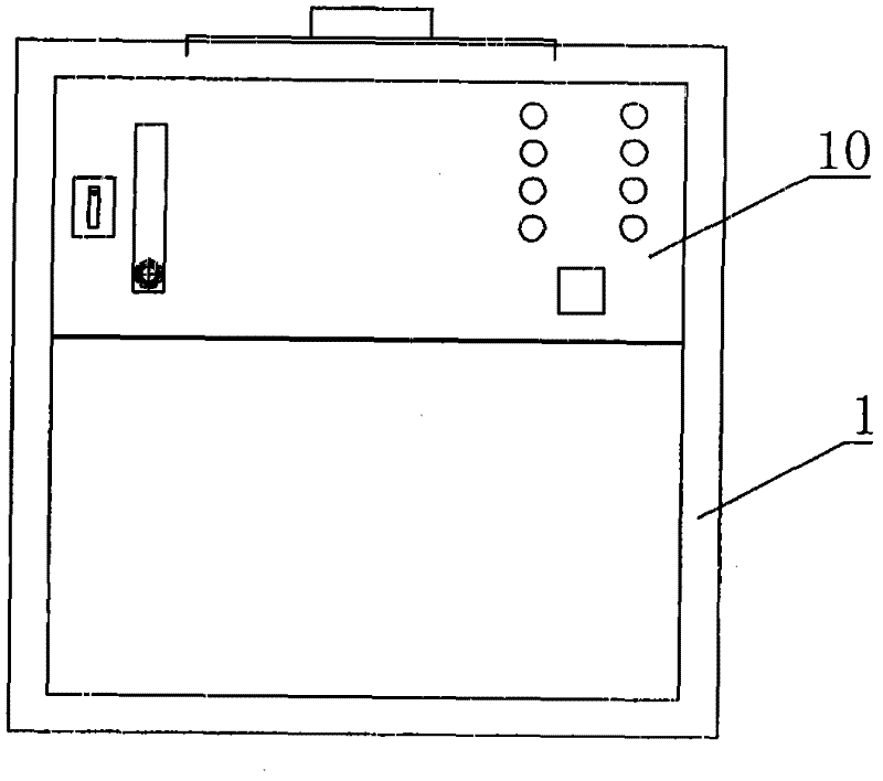
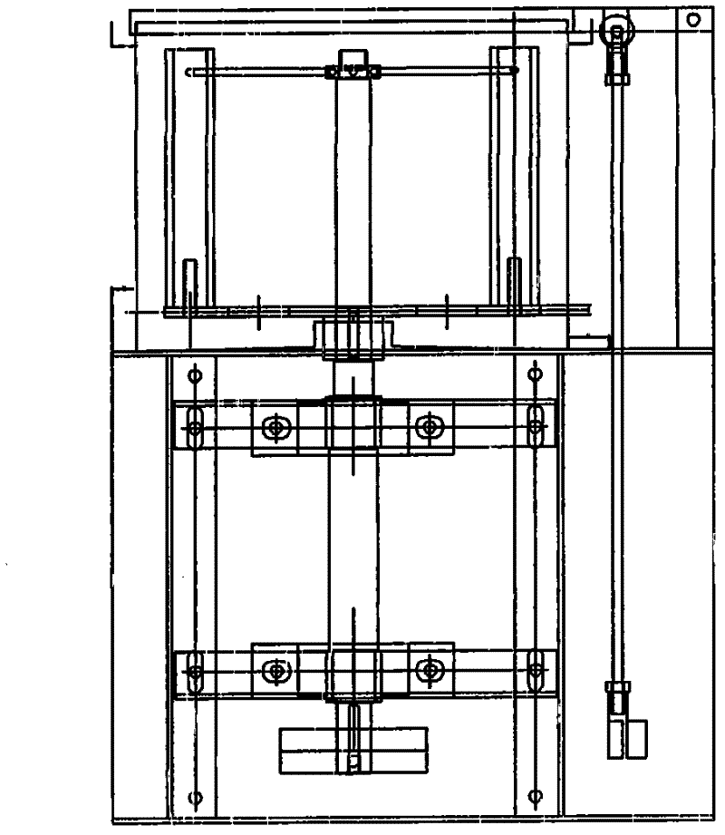
[0015] Such as figure 1 , 2 , 3, including frame 1, dehydration outer barrel 2, barrel cover 3, rotating shaft 4, drive motor 5,

[0016] The top of the above-mentioned frame 1 is fixed with a dehydration outer barrel 2, the top of the dehydration outer barrel 2 is covered with a barrel cover 3 for sealing, and the side wall of the outer barrel is provided with an air inlet through which nitrogen gas can be introduced to prevent diode It is oxidized in contact with air during dehydration.

[0017] Rotating shaft 4 is vertically arranged on frame 1 by bearing and bearing seat, and its top stretches into the center of dehydration outer barrel 2, and the end is connected with drive motor 5 by belt transmission.

[0018] The dehydration liner is set in the dehydration outer barrel 2, and is used to install the diode pickling mold that needs dehydration. It mainly includes a bottom plate 6, a vertical support 7, six vertical support 7 evenly distributed around the circular bottom...


PUM


Abstract

The invention relates to a light-emitting diode dehydrator, which comprises a rack, and has the innovative points that: the light-emitting diode dehydrator further comprises a dehydration outer barrel, a rotating shaft, a dehydration inner container and a control system, wherein the dehydration outer barrel is fixedly arranged at the top end of the rack, and a barrel cover for sealing is arranged at the barrel top; the rotating shaft is vertically arranged on the rack, the upper part of the rotating shaft extends into the center of the dehydration outer barrel, and the rear end of the rotating shaft is connected with a drive motor through a transmission mechanism; the dehydration inner container is used for installing a light-emitting diode acid-washing mould to be dehydrated, and is arranged in the dehydration outer barrel, and the center of the dehydration inner container is fixed with the rotating shaft which extends into the dehydration outer barrel; and the control system comprises a programmable controller and a control panel thereof, and the programmable controller is connected with the drive motor. The invention has the advantages that: when the dehydration is carried out, the two ends of the light-emitting diode acid-washing mould are inserted into an installation groove of the light-emitting diode acid-washing mould of the vertical rack of the dehydration inner container, then the barrel cover is closed, the drive motor is started through the control panel, the rotating shaft drives the dehydration inner container to rotate, the water in the light-emitting diode is dehydrated through the centrifugal force, so the dehydration is realized. The gas inlet of the side wall of the dehydration outer barrel can be filled with nitrogen, so the light-emitting diode is prevented from being oxidized during the dehydration.

Description

technical field [0001] The invention relates to a diode dehydrator, in particular to a diode dehydrator with good dehydration effect. Background technique [0002] In the production process of diodes, pickled diodes need to be washed with water to remove residual acid, and dehydrated after washing. The traditional dehydration method uses ethanol dehydration, which is not complete and the effect is poor. Contents of the invention [0003] The technical problem to be solved by the invention is to provide a diode dehydrator with good dehydration effect. [0004] In order to solve the above technical problems, the technical solution of the present invention is: a diode dehydrator, including a frame, and its innovative point is that it also includes a dehydration outer barrel, which is fixed on the top of the frame, and the top of the barrel is provided with a sealing cover; A rotating shaft, vertically set on the frame, the upper part extends into the center of the dehydratio...

Claims


Application Information

Patent Timeline
IPC IPC(8): F26B11/08F26B5/08
Inventor 李树
Owner RUGAO DACHANG ELECTRONICS
Why Eureka
Try Eureka