Continuous drying chamber for wet ceramic green

A drying chamber and wet billet technology, which is applied in the field of sanitary ceramics wet billet drying equipment, can solve the problems that the loading and unloading of transfer vehicles cannot be done too high, the space cannot be used effectively, and the heat in the drying chamber is uneven, etc., to achieve increased Space utilization, area saving, good drying effect

Active Publication Date: 2012-04-11
HUIDA SANITARY WARE
View PDF7 Cites 18 Cited by
  • Summary
  • Abstract
  • Description
  • Claims
  • Application Information

AI Technical Summary

Problems solved by technology

[0002] In the traditional ceramic molding wet billet drying process, the drying method of ordinary drying room has been adopted. The wet billet is manually loaded on the transfer car and pushed into the drying room. After the drying is completed, the dry billet is removed, which is easy to cause damage.

Method used


Image

  • Continuous drying chamber for wet ceramic green
  • Continuous drying chamber for wet ceramic green
  • Continuous drying chamber for wet ceramic green

Examples


Embodiment Construction

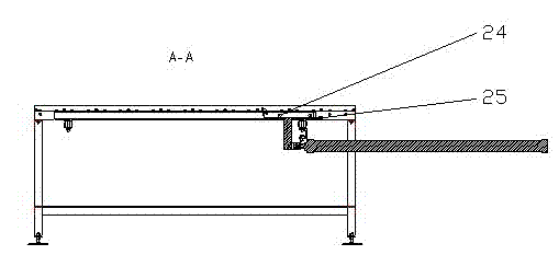
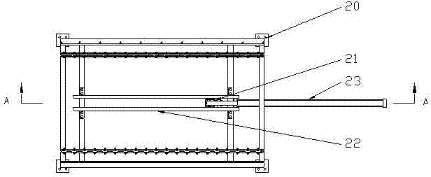
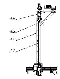
[0030] The present invention consists of a drying chamber body 1, a drying chamber inlet conveying line 2, a propulsion lifting mechanism 3, a roller shelf 4, a receiving and lifting mechanism 5, a drying chamber outlet conveying line 6, a hot air mixer 7, a heating device 8, and a moisture discharge Device 9, composed of PLC control device.

[0031] Show in the figure, overall structure of the present invention is:

[0032] Inside the drying chamber body 1, the drying chamber inlet conveying line 2, the propulsion and lifting mechanism 3, the roller shelf 4, the receiving and lifting mechanism 5, and the drying chamber outlet conveying line 6 are arranged in sequence in the form of an assembly line. Two groups of roller racks 4 are installed between the advancing mechanism 3 and the receiving lifting mechanism 5, the advancing hoist 27 is fixed by advancing the upper track 11 and the lower track 12, and can walk along the track before the roller shelf 4, and the receiving hoi...


PUM


Abstract

The invention discloses a continuous drying chamber for a wet ceramic green, belonging to the technical field of ceramic production equipment and used for automatic drying in production of molded wet ceramic green. In a technical scheme disclosed by the invention, the continuous drying chamber is composed of a drying chamber main body, a drying chamber inlet conveying line, an advancing and lifting mechanism, roller shelves, a receiving and lifting mechanism, a drying chamber outlet conveying line, hot air stirrers, a heat supply device, a dampness removing device and a PLC (Programmable Logic Controller) system, wherein the advancing and lifting mechanism and the receiving and lifting mechanism are arranged at two ends of the drying chamber and are respectively the drying chamber inlet conveying line and the drying chamber outlet conveying line, the roller shelves are arranged between the advancing and lifting mechanism and the receiving and lifting mechanism, a plurality of hot air stirrers are arranged among the roller shelves, the heat supply device and the dampness removing device are respectively communicated with the drying chamber main body, and the PLC control device is respectively connected with the mechanisms and devices. According to the invention, the automatic drying of molded wet ceramic green is realized without manual carrying, damages caused by manual operation are avoided, the utilization rate of a production field is increased, and the drying effect is enhanced.

Description


Claims


Application Information

Patent Timeline
Owner HUIDA SANITARY WARE
Why Eureka
Try Eureka