Stimulated Raman scattering (SRS) compensation method in distributed optical fiber temperature sensor system

A technology of stimulated Raman scattering and temperature sensor, applied in thermometers, thermometers with physical/chemical changes, instruments, etc., can solve the problems of stimulated Raman scattering, stimulated Raman scattering, etc. Noise, the effect of improving the accuracy of temperature measurement

Active Publication Date: 2012-04-11
BEIJING AEROSPACE TIMES OPTICAL ELECTRONICS TECH
View PDF4 Cites 12 Cited by
  • Summary
  • Abstract
  • Description
  • Claims
  • Application Information

AI Technical Summary

Problems solved by technology

The longer the transmission distance, the higher the pump light power is required, and the higher pump light power and the longer transmission distance will easily lead to the occurrence of stimulated Raman scattering (because the stimulated Raman scattering threshold varies with the pump The higher the accuracy of the distributed optical fiber temperature sensor, the greater the signal-to-noise ratio. The increase in the signal-to-noise ratio requires an increase in the signal optical power on the one hand, and on the other hand requires a reduction in noise, while the signal-to-noise ratio increases. The increase of optical power requires the increase of pump optical power, which also easily leads to the occurrence of stimulated Raman scattering

Method used


Image

  • Stimulated Raman scattering (SRS) compensation method in distributed optical fiber temperature sensor system
  • Stimulated Raman scattering (SRS) compensation method in distributed optical fiber temperature sensor system
  • Stimulated Raman scattering (SRS) compensation method in distributed optical fiber temperature sensor system

Examples


Embodiment

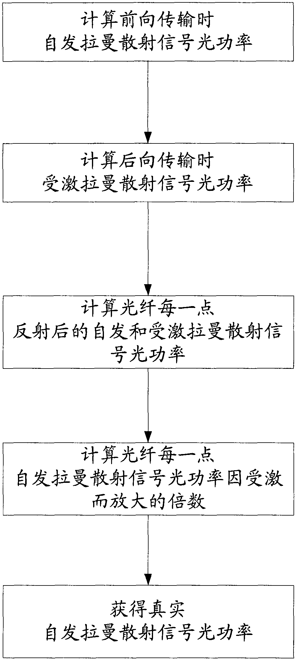
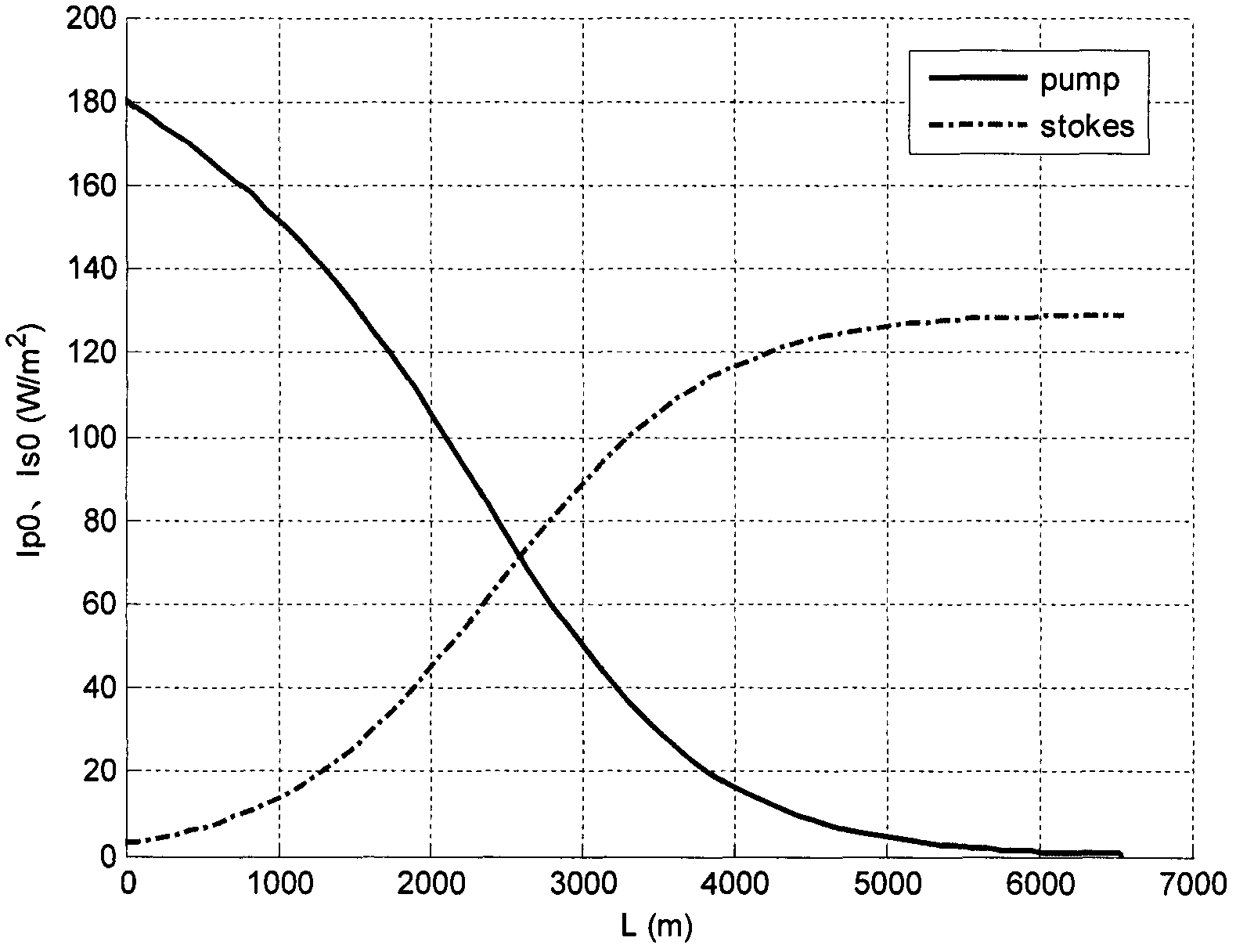
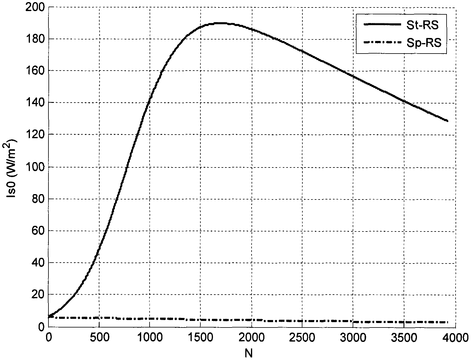
[0055] (1) Carry out theoretical calculation first. The main parameters are selected as follows: pump light peak power P p =10W, effective core section A eff =3068μm 2 , fiber length L=6550m, pump light pulse width T 0 =10ns, absolute temperature T=300k, fiber refractive index n=1.5.

[0056] (2) According to the selected parameters, use the following formula to calculate the light intensity I of the backward transport pump light p0 (L=6550m) and backward transmission signal light intensity I s0 (L=6550m)

[0057] I p0 (L=6550)=I' p0 (0)exp(-α p ×6550)Γ p (1)

[0058] I s 0 ( L = 6550 ) = 1 2 v ρ s I p 0 ( 6550 ) ...


PUM

PropertyMeasurementUnit
refractive indexaaaaaaaaaa

Abstract

The invention discloses a stimulated Raman scattering (SRS) compensation method in a distributed optical fiber temperature sensor system. The method comprises the following steps of: (1) at specific pumping light power and specific optical fiber length (L), calculating the backward transmission light intensity after the optical power of a forward transmitted self-emitted Raman scattering signal is subjected to Rayleigh scattering at the L and the backward transmission light intensity after the pumping light is subjected to forward transmission and Rayleigh scattering at the L; (2) calculatinga stimulated scattering process by using the numerical value of a RungeKutta method to obtain SRS signal light; (3) acquiring a self-emitted Raman scattering signal and an SRS signal at a random point z of an optical fiber according to the step (2); (4) acquiring the magnification of the self-emitted Raman scattering signal due to stimulation; and (5) acquiring a real Raman scattering signal according to the magnification. By the method, the influence of SRS can be eliminated, and the precision of temperature measurement is improved.

Description

technical field [0001] The invention discloses a method for compensating stimulated Raman scattering in a distributed optical fiber temperature sensor system. Background technique [0002] Distributed optical fiber temperature sensor is a kind of optical fiber sensing system developed in recent years for real-time measurement of space temperature field. The system uses Raman scattering effect and OTDR technology to realize the distributed measurement of the temperature field where the sensitive optical fiber is located. Compared with traditional electrical temperature sensors, optical fiber temperature sensors have the advantages of high sensitivity, strong electromagnetic interference resistance, intrinsic safety, light weight, long life, and high reliability, and can be widely used in power cables, subway tunnels, coal mine roadways, and oil storage tanks , Temperature monitoring and fire alarm for large building structures. Although the research on Raman-type distribute...

Claims


Application Information

Patent Timeline
Patent Type & Authority Applications(China)
IPC IPC(8): G01K11/32G01K11/324
Inventor 王巍王学锋李小彦蓝天杨潇君赵政鑫
Owner BEIJING AEROSPACE TIMES OPTICAL ELECTRONICS TECH
Why Eureka
Try Eureka