Indirectly driven traction type pumping unit

A pumping unit and traction technology, which is used in the production of fluids, wellbore/well components, and earth-moving drilling, etc., can solve the problems of insufficient loss-of-load protection, limited application environment, limited traction force, etc., to increase the service life and Safety factor, increased safety, and the effect of balanced force distribution

Active Publication Date: 2012-04-18
王宇博
View PDF11 Cites 3 Cited by
  • Summary
  • Abstract
  • Description
  • Claims
  • Application Information

AI Technical Summary

Problems solved by technology

[0009] The purpose of the present invention is to provide an indirect drive traction pumping unit, which fundamentally solves the problems of the existing traction pumping units such as limited traction force, short belt life, insufficient protection against loss of load, and limited application environment. Compared with similar products, it has reasonable design, balanced force distribution, compact structure, small size, light weight, low cost, safe and reliable operation, large traction force, high transmission efficiency, convenient installation and maintenance of the whole machine, and wide application range. wide advantages

Method used


Image

  • Indirectly driven traction type pumping unit
  • Indirectly driven traction type pumping unit
  • Indirectly driven traction type pumping unit

Examples


Embodiment Construction

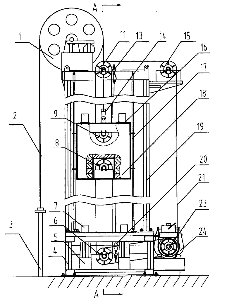
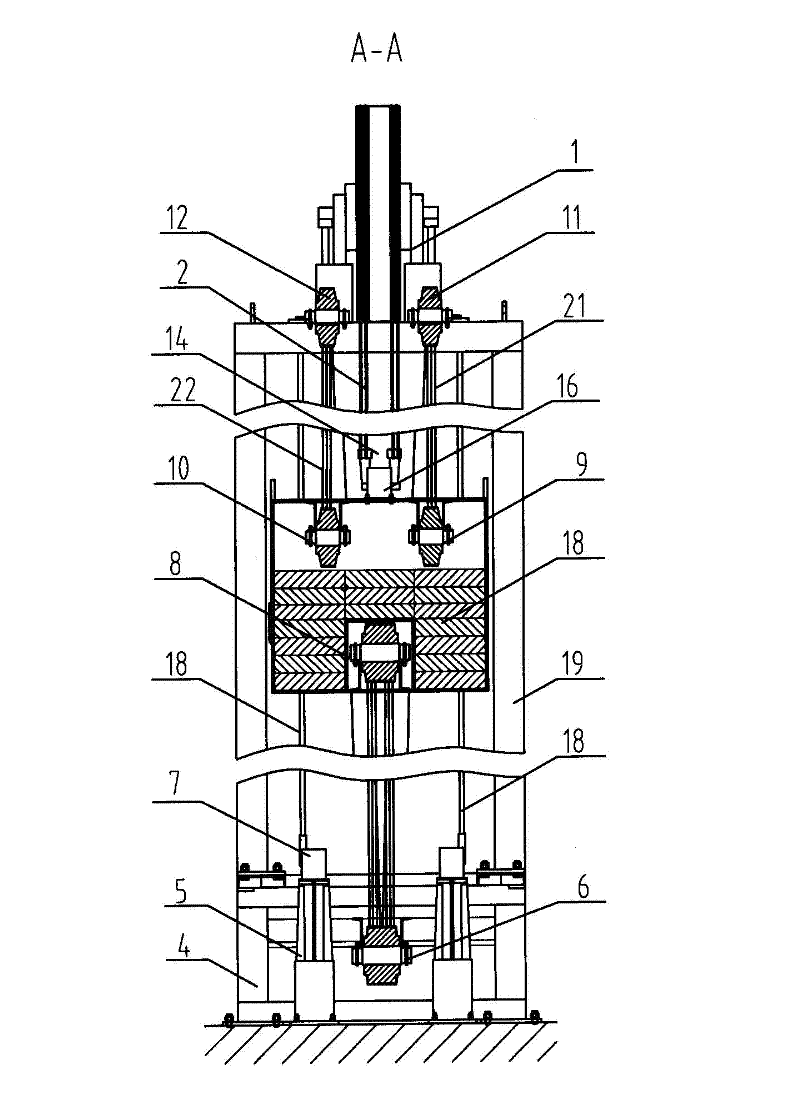
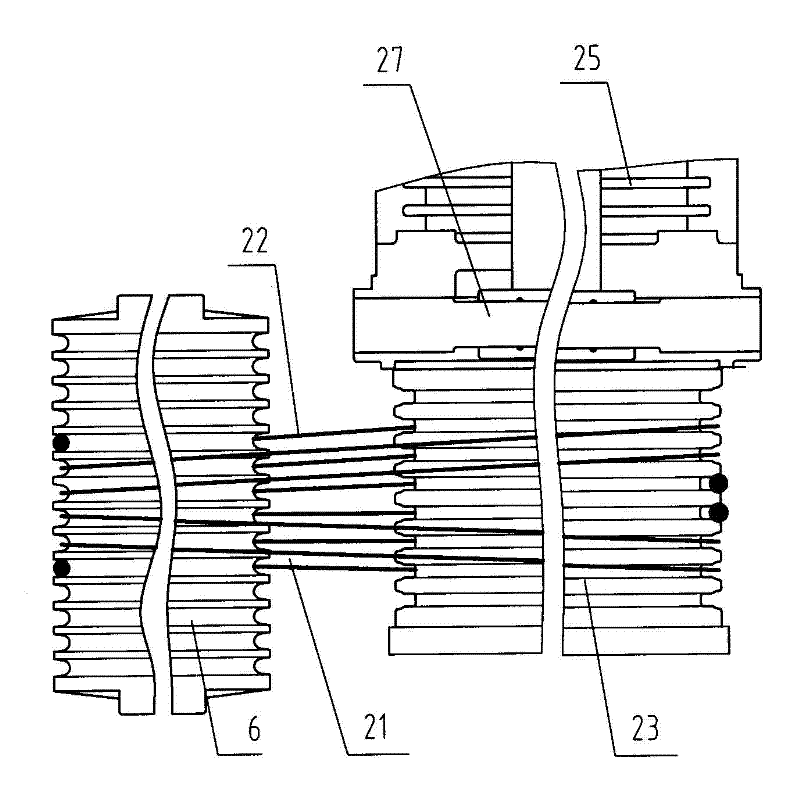
[0028] according to Figure 1~5 The specific structure of the present invention will be described in detail. The indirect drive traction pumping unit includes a frame 19, a frame 4, a suspension device arranged on the frame 19, a traction device and the like. Among them, the suspension device has no traction power, and basically only plays the role of balancing bearing capacity. It includes an upper suspension wheel 1 arranged on the top of the frame 19. The upper suspension wheel 1 suspends the sucker rod 3 and the counterweight 18 respectively on both sides of the upper suspension wheel 1 through the suspension steel wire rope 2. Oil, the counterweight 18 moves up and down inside the frame 19 along the guide rail 17. The last suspension wheel 1 that is arranged on frame 19 tops is a non-powered mechanism, only plays suspension and guiding effect, so its diameter can be done very big. The diameter of suspension wire rope 2 depends on the hanging weight of suspension device...


PUM


Abstract

The invention discloses an indirectly driven traction type pumping unit, which radically solves the problems of limited traction force, limited application environment and the like of the conventional traction type pumping unit. The pumping unit comprises a frame, a base, a hanging device and a traction device. The pumping unit is characterized in that: upper and lower motor seats for fixing a permanent magnet synchronous motor are respectively arranged on the frame and the base; a traction wheel of the traction device is assembled together with a rotor on a driving main shaft of the permanent magnet synchronous motor, and a coder is arranged at the end of the main shaft of the permanent magnet synchronous motor; drum-type gate arms are arranged on two sides of a brake wheel and connected with electromagnetic brakes on the upper part of the permanent magnet synchronous motor; left and right traction steel wire ropes are respectively wound on the same traction wheel in the same direction, and one end of each of the steel wire ropes goes around a lower pulley block and is fixed on the base; and the other ends of the steel wire ropes respectively go around a guide wheel and two upper pulley blocks fixed on the frame and are fixed on the frame. Compared with similar products, the pumping unit has the advantages of reasonable design, low cost, safety and reliability in operation, large traction force, high transmission efficiency and wide application range.

Description

technical field [0001] The invention relates to a traction type oil pumping unit, in particular to an indirect drive traction type oil pumping unit which is suitable for low-lying areas where water often accumulates or shallow sea areas, and for areas with strong winds and frequent maintenance. It can replace large oil beam machines of type 20 or above, and belongs to the technical field of oil field production machinery. Background technique [0002] At present, most of the pumping units used in my country's oilfields are beam pumping units, which have a relatively simple structure, durability, and convenient maintenance and operation, but have low transmission efficiency, high energy consumption, many consumables, and intelligence. low-level defects. In order to overcome the above shortcomings and respond to the national call for energy conservation and emission reduction, people pay more and more attention to traction pumping units, and heavy traction pumping units are mo...

Claims


Application Information

Patent Timeline
Patent Type & Authority Applications(China)
IPC IPC(8): E21B43/00
Inventor 王宇博
Owner 王宇博
Why Eureka
Try Eureka