Low-resistivity spring-free jig and manufacturing method thereof

A technology without springs and fixtures, used in the manufacture of measuring instruments, measuring devices, instruments, etc., can solve the problems of high low resistance requirements, inability to meet the high density and low resistance requirements of printed circuit boards, etc., and reduce contact resistance. , The effect of solving the low resistance test of the fixture and improving the test accuracy

Active Publication Date: 2012-04-18
珠海拓优电子有限公司
View PDF7 Cites 3 Cited by
  • Summary
  • Abstract
  • Description
  • Claims
  • Application Information

AI Technical Summary

Problems solved by technology

[0005] As the printed circuit board test points become denser, the solder joints become finer, and the requirements for low resistance become higher and higher, the existing fixtures can no longer meet the requirements High Density, Low Resistance Requirements for Printed Circuit Board Testing

Method used


Image

  • Low-resistivity spring-free jig and manufacturing method thereof
  • Low-resistivity spring-free jig and manufacturing method thereof
  • Low-resistivity spring-free jig and manufacturing method thereof

Examples


Embodiment approach 1

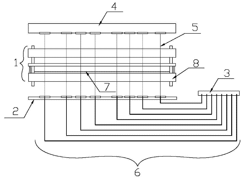
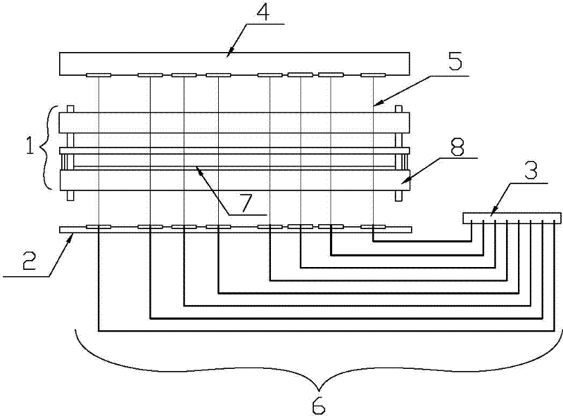
[0033] Implementation mode one: if figure 1 As shown, the low-resistance springless jig includes a needle plate 1, a wire plate 2 and a test interface 3. The needle plate 1 is composed of three insulating boards, and has through holes corresponding to the test points of the board 4 to be tested. The probe 5 is placed in the hole; the reel 2 is composed of an insulating plate, and a hole corresponding to the through hole on the lower surface of the needle disc is opened, and the wire 6 is placed in the hole, and the other end of the wire 6 is connected to the test interface 3 by welding superior. The diameter of the probe 5 is between 0.05mm and 0.15mm, and it is made of piano steel wire or rhenium tungsten wire.

[0034] The probe 5 is coated with insulating varnish or wrapped with an insulating layer except that both ends are exposed. The exposed parts of both ends of the probe 5 are electroplated with a layer of nickel, and the nickel is electroplated with a layer of gold...


PUM


Abstract

The invention relates to a low-resistivity spring-free jig and a manufacturing method thereof. The conventional jig cannot meet the requirements of high density and low resistance values of a printed circuit board during testing. Therefore, the low-resistivity spring-free jig comprises a needle disc, a wire coil and a testing interface, wherein the needle disc consists of one or more insulating boards and is provided with a through hole corresponding to a testing point of a board to be tested, and a probe is arranged in the through hole; the wire coil consists of one or more insulating boards and is provided with a hole corresponding to the through hole on the lower surface of the needle disc, a conducting wire is arranged in the hole, and the other end of the conducting wire is connected to the testing interface; the probe has the diameter of between 0.015 and 0.15mm and is made of a piano wire or a rhenium-tungsten wire; the needle disc is pressed on the wire coil; and the probe is pressed at the upper end of a corresponding conducting wire. The invention also relates to a method for manufacturing a corresponding jig. The low-resistivity spring-free jig has the advantages of simple structure, low resistance value and high density and is widely applied in the process of detecting various printed circuit boards.

Description

technical field [0001] The invention relates to a low-resistance springless jig and a manufacturing method thereof. Background technique [0002] The electronic components on the circuit board should be connected in series or in parallel with an appropriate circuit to achieve a specific function. In the event of a short or open circuit, the board will not be usable. Therefore, the circuit board must be tested before leaving the factory. The circuit on the circuit board is complex and the number of electronic components is too large. During the testing process of electronic components, it is necessary to rely on test fixtures and cooperate with the test host to complete the testing of electronic components. [0003] The existing test fixture is a probe press-type fixture, which consists of a needle plate, a wire plate, a probe, a spring connection, and a test interface; the needle plate is composed of one or more insulating plates, and the needle plate has The probe is plac...

Claims


Application Information

Patent Timeline
Patent Type & Authority Applications(China)
IPC IPC(8): G01R3/00G01R1/067
Inventor 郭红建
Owner 珠海拓优电子有限公司
Why Eureka
Try Eureka