Practical layering and zoning reactive power optimization method on basis of power grid real time data

A technology of real-time data and optimization methods, applied in reactive power compensation, reactive power adjustment/elimination/compensation, etc., can solve problems such as large amount of calculation, poor stability, and impossibility to deal with large systems

Inactive Publication Date: 2012-04-18
NORTH CHINA ELECTRIC POWER UNIV (BAODING) +1
View PDF2 Cites 24 Cited by
  • Summary
  • Abstract
  • Description
  • Claims
  • Application Information

AI Technical Summary

Problems solved by technology

However, these methods more or less have the problems of large amount of calculation, poor convergence, poor stability, and easy to fall into the local optimal solution and converge earl

Method used


Image

  • Practical layering and zoning reactive power optimization method on basis of power grid real time data
  • Practical layering and zoning reactive power optimization method on basis of power grid real time data
  • Practical layering and zoning reactive power optimization method on basis of power grid real time data

Examples


Embodiment 1

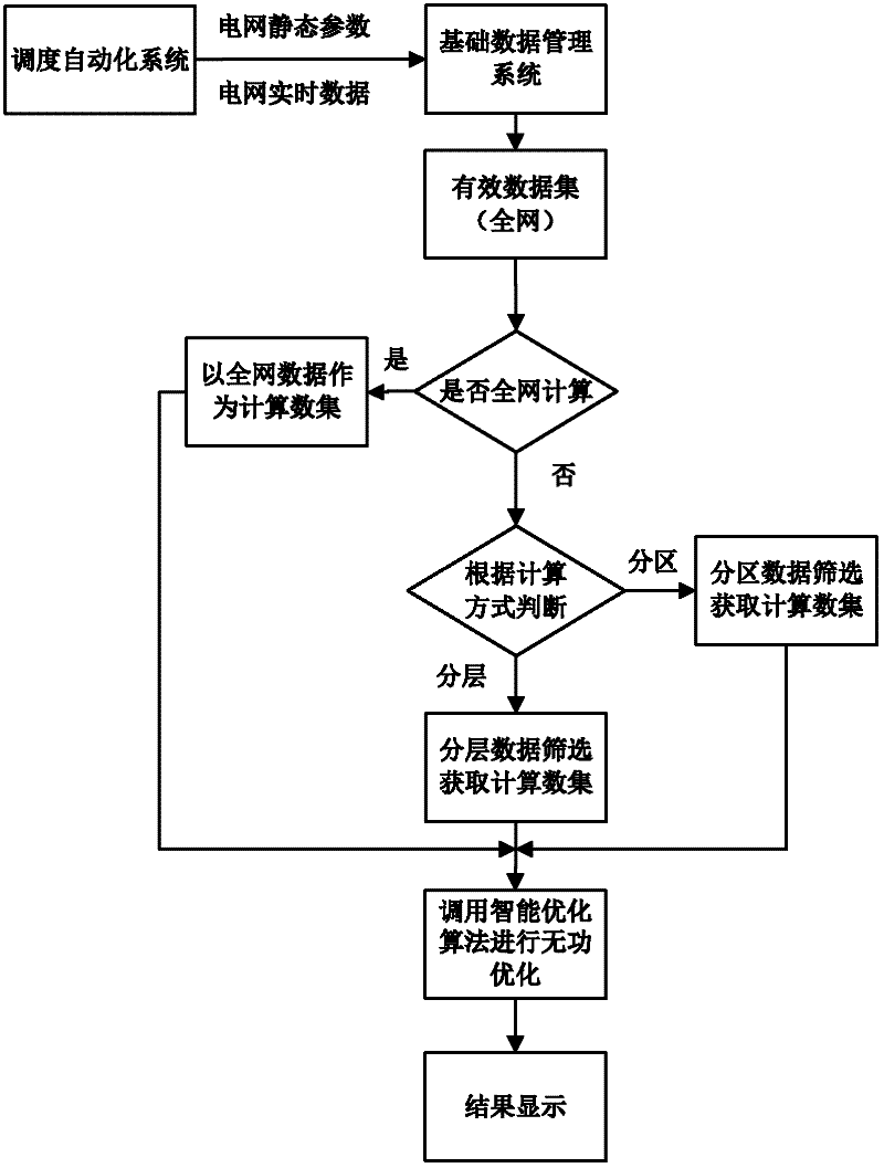
[0030] figure 1 It is a flow chart of the reactive power optimization method based on the real-time data of the power grid. In this example, the reactive power optimization method layered according to the 330kV voltage level is adopted, and the method includes:

[0031] Step 1: Read in data information. Data information includes grid static parameters, constraints and real-time data; among them, grid static parameters and constraints are the data provided by the energy management system for static analysis of the grid, and grid real-time data is output by the energy management system to reflect the real-time operation of the grid State calculation data;

[0032] Step 2: Obtain valid data for power flow calculation. According to the live identification and power grid topology information in the data information, the data set that the whole network can participate in the calculation is extracted. It mainly includes the data of generators, lines, transformers, shunt compensat...

Embodiment 2

[0046] figure 1It is a flow chart of the reactive power optimization method based on the real-time data of the power grid. In this example, the reactive power optimization method based on user needs partitioning is adopted, and the method includes:

[0047] Step 1: Read in data information. Data information includes grid static parameters, constraints and real-time data.

[0048] Step 2: Obtain valid data for power flow calculation. According to the live identification and power grid topology information in the data information, the data set that the whole network can participate in the calculation is extracted. It mainly includes data sets of generators, lines, transformers, shunt compensation devices and loads.

[0049] Step 3: Determine that the calculation method is partition optimization, and then filter the corresponding calculation data according to the calculation method of partition reactive power optimization. The screening method is as follows.

[0050] 1. Clic...


PUM


Abstract

The invention discloses a practical layering and zoning reactive power optimization method on the basis of power grid real time data in the technical field of the reactive power optimization of a power grid, which comprises the following steps of: reading in data information which comprises a power grid static parameter, a constraint condition and the power grid real-time data; acquiring effective data for power flow calculation from the read data information; determining an optimization mode and screening the effective data according to the optimization mode; and calculating to obtain a reactive power optimization result by adopting a reactive power optimization method on the basis of an improved immune genetic algorithm. In the method, the number of nodes in an area is effectively controlled by layering according to the voltage class or zoning according to a designated area, so that the calculating time is greatly shortened. Moreover, due to the adoption of the improved immune genetic algorithm, the problem of involving in local optimal solution to converge in advance is avoided.

Description

technical field [0001] The invention belongs to the technical field of power grid reactive power optimization control, in particular to a reactive power optimization method based on power grid real-time data. Background technique [0002] Since the concept of smart grid was put forward, the State Grid Corporation of China has attached great importance to it, and put forward the strategic development goal of building a strong smart grid with Chinese characteristics. Improving the power quality of the grid and reducing the active power loss of the entire grid through reactive power optimization is an indispensable task for building a smart grid, which is of great significance to the safety, stability, and economic operation of the grid. [0003] The so-called reactive power optimization control problem of the power grid refers to adjusting the reactive power flow by adjusting the terminal voltage of the generator, adjusting the tap of the transformer and changing the compensat...

Claims


Application Information

Patent Timeline
IPC IPC(8): H02J3/18
CPCY02E40/30
Inventor 刘文颖郑伟徐鹏梁琛曹俊龙郑晶晶门德月梁福波邢晶李波吴耀浩李亚龙钟佳辰文晶谢昶王久成刘茜周海洋吴晓丹
Owner NORTH CHINA ELECTRIC POWER UNIV (BAODING)
Why Eureka
Try Eureka