Method for preparing high-brightness flowing luminescence electric wire

A luminous wire, high-brightness technology, applied in the field of electroluminescent devices, can solve the problems of data wire frequency signal interference, limit the use of luminous wires, and thick wires, etc.

Inactive Publication Date: 2014-12-10
SHANGHAI DONGZHOU IND
View PDF6 Cites 0 Cited by
  • Summary
  • Abstract
  • Description
  • Claims
  • Application Information

AI Technical Summary

Problems solved by technology

In the prior art, the luminous wire and the functional wire work separately and independently, and the wire body is thick. At the same time, the high-frequency electroluminescent wire produces serious frequency signal interference to the data wire used for communication; in addition, due to the structural design of the existing luminous wire, it can only With simple and regular direction flashing, the above deficiencies limit the use of light-emitting wires

Method used


Image

  • Method for preparing high-brightness flowing luminescence electric wire
  • Method for preparing high-brightness flowing luminescence electric wire
  • Method for preparing high-brightness flowing luminescence electric wire

Examples


preparation example Construction

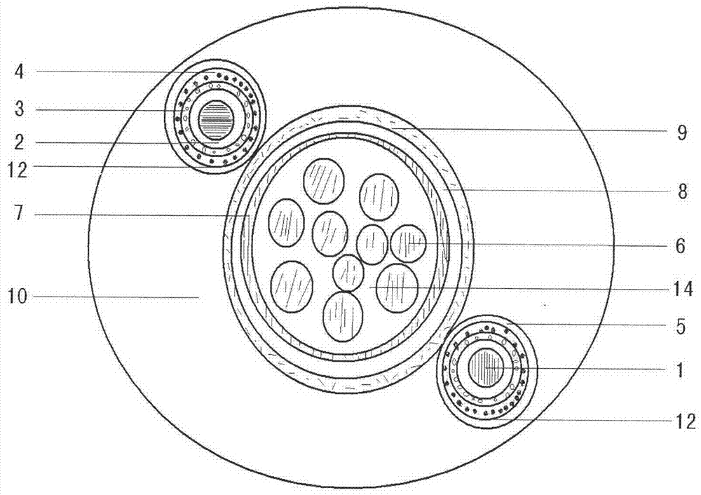
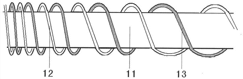
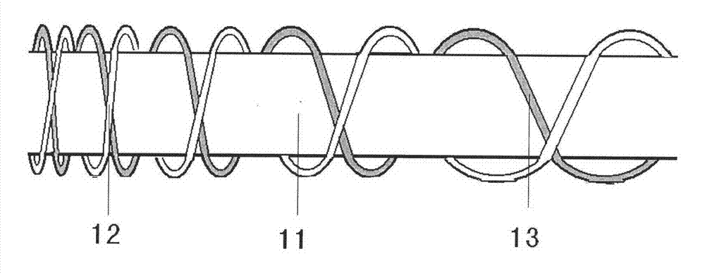
[0028] A preparation of a high-brightness flowing luminous wire, which includes: a central data line 11, a plurality of luminous lines 12, and an outer transparent plastic protective layer 10; a plurality of luminous lines are wound in parallel or crossed on the outside of the central data line, and the luminous lines It can be regularly combed and combined during winding, and better results can be produced during dynamic changes; and it is completely wrapped by the outer transparent plastic protective layer 10. The transparent plastic protective layer uses materials such as PVC, PE, PU, ​​etc., which can be It is colorless and transparent, or it can be colored and transparent with fluorescence, so as to prepare colored luminous lines. Adding 0.1-10% fluorescent whitening agent can effectively improve the luminous uniformity and luminous intensity. The inner conductive layer 9 outside the central data line and the metal core 1 of the light-emitting line are respectively connect...

Embodiment

[0038] In the preparation of a high-brightness flowing luminous wire of the present invention, the central data line is made of multi-strand copper metal wire with a diameter of 1 mm, the inner insulating layer is coated with polyurethane, the metal shielding coating is coated with silver paste, and the insulating layer is coated with polyurethane. The inner conductive layer uses a silver paste layer, and the above are prepared one by one by infrared temperature curing.

[0039] Instructions for the use of the metal core of the central luminous line of the present invention is 0.1mm copper wire. The medium layer of the luminous line is made of copper calcium titanate coating film. The most important is the nano-zinc oxide nano-material coating film, and the transparent conductive layer of the luminescent line uses the ATO transparent conductive material coating film. The adhesive applied above uses fluorine-containing paint, which is cured by infrared heating, and the coating ...


PUM


Abstract

The invention discloses a method for preparing a high-brightness flowing luminescence electric wire. The high-brightness flowing luminescence electric wire comprises a central data wire 11, a plurality of luminescence wires 12 and an external transparent plastic protection layer 10, wherein the plurality of luminescence wires are wound outside the central data wire according to a principle in a parallel or crossed mode and completely covered by the external transparent plastic protection layer 10; an internal conducting layer 9 outside the central data wire and luminescence wire metal cores 1 are respectively connected to two electrodes of an alternating current to generate luminescence under a voltage of 110 V to 220 V and at a frequency of 50 Hz; and a plurality of luminescence wire metal cores 1 are respectively controlled by using a plurality of paths of special controllers to generate flowing luminescence having a direction principle. The high-brightness flowing luminescence electric wire can be applied to luminescence electric wire identifiers, luminescence data wires, safety indication marks and the like.

Description

technical field [0001] The invention belongs to the technical field of electroluminescent devices application. Background technique [0002] The existing luminescent wires are mainly manufactured simply by using electroluminescent wires directly accompanied by an insulated wire. The structure of the electroluminescent wires is mainly a metal core electrode, an insulating medium layer, a luminescent layer, a transparent conductive layer, and a wound outer electrode. When the metal core electrode and the winding outer electrode are connected with a voltage of 80-150V, light will be generated. This structure, material, and formula have been clearly described in Chinese patents 200680032428.8 and 200410099233.8. The flashing of the electroluminescent wire uses a winding structure of multiple metal core electrodes. By controlling the opening and closing of the circuit, a single flashing multi-wire combination is completed, and the overall control is cycled segment by segment to a...

Claims


Application Information

Patent Timeline
Patent Type & Authority Patents(China)
IPC IPC(8): H05B33/12
Inventor 耿树范边静宇郑岩
Owner SHANGHAI DONGZHOU IND
Why Eureka
Try Eureka