Self-sealing variable-frequency oil gun and control method thereof

A frequency conversion control and refueling gun technology, applied in special distribution devices, packaging, distribution devices, etc., can solve the problems of unfavorable stability and safety of the hydraulic system, high pressure, energy waste, etc., to reduce processing difficulty and performance requirements , reduce resistance and improve pumping efficiency

Active Publication Date: 2012-04-25
SOUTH CHINA UNIV OF TECH
View PDF5 Cites 3 Cited by
  • Summary
  • Abstract
  • Description
  • Claims
  • Application Information

AI Technical Summary

Problems solved by technology

[0004] 1. Conventional self-styled refueling guns control the refueling flow by adjusting the opening of the main valve. When the required flow is large, the opening of the main valve is increased; Running at full speed, this kind of operation will inevitably cause a waste of energy
[0005] 2. After the oil gun is self-sealing, the motor of the fuel dispenser is still running at full speed. At this time, all the flow pumped up by the pump flows back to the oil tank through the overflow valve, which not only causes a lot of energy waste, but also makes the internal pressure of the system very high. , which is extremely detrimental to the stability and safety of the entire hydraulic system
However, this mode is applied to the existing self-sealing refueling gun, and a number of improvements must be made to better utilize the existing mature technology and achieve the goals of energy saving and safety.

Method used


Image

  • Self-sealing variable-frequency oil gun and control method thereof
  • Self-sealing variable-frequency oil gun and control method thereof
  • Self-sealing variable-frequency oil gun and control method thereof

Examples


Embodiment

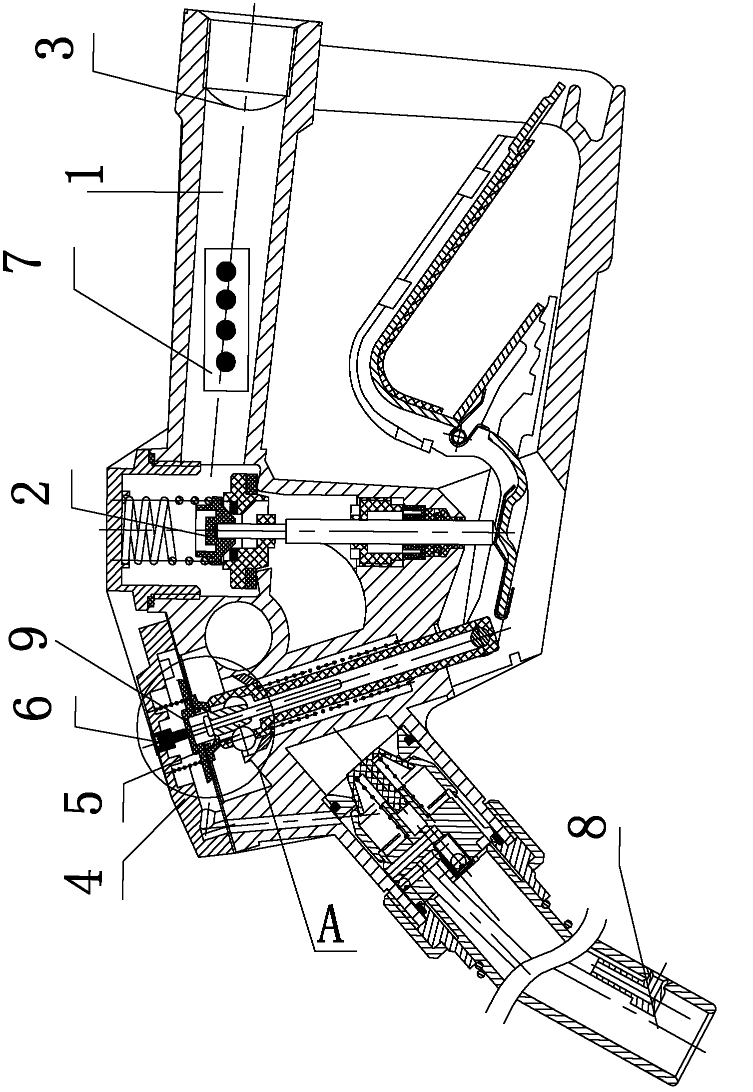
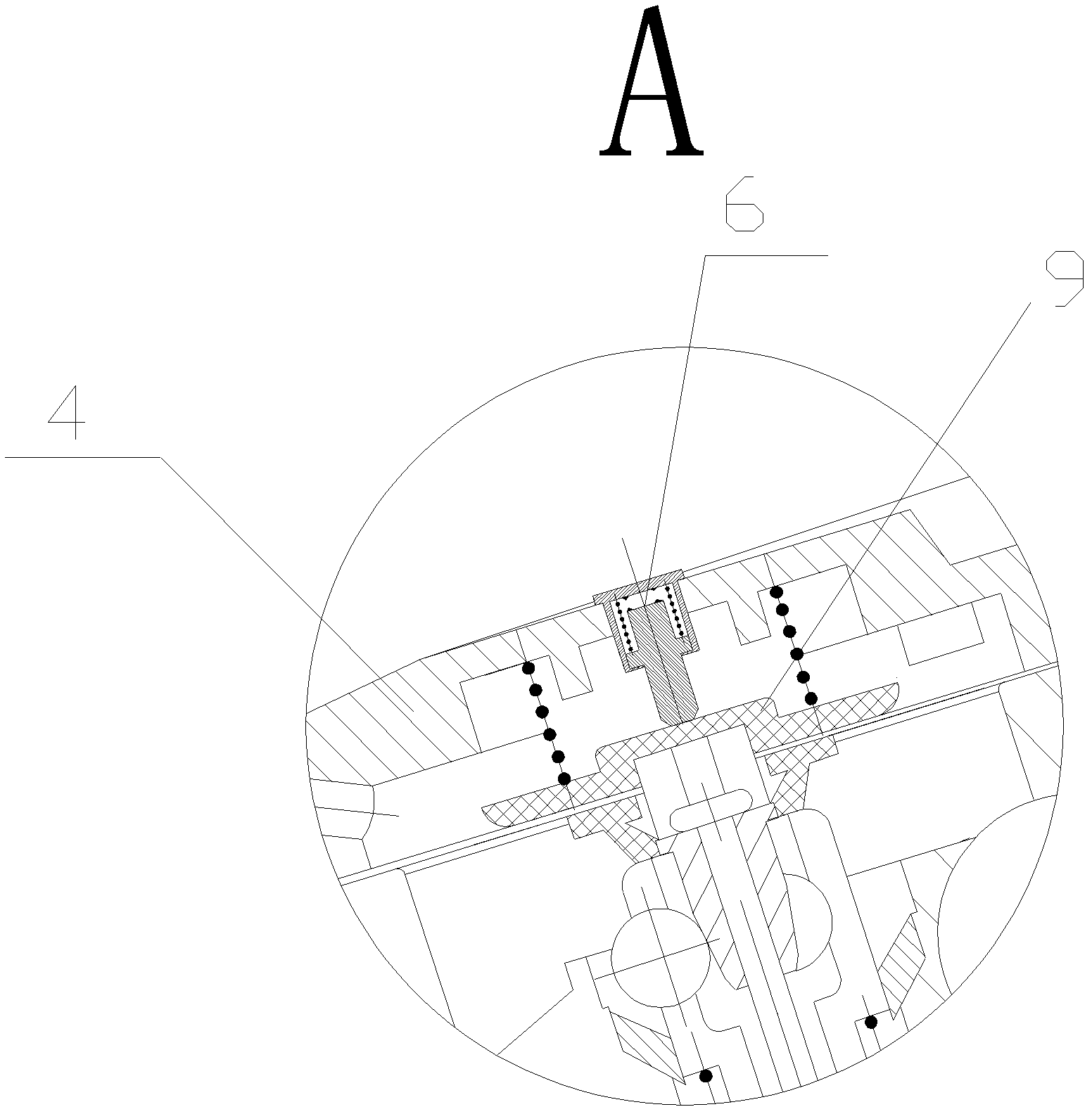
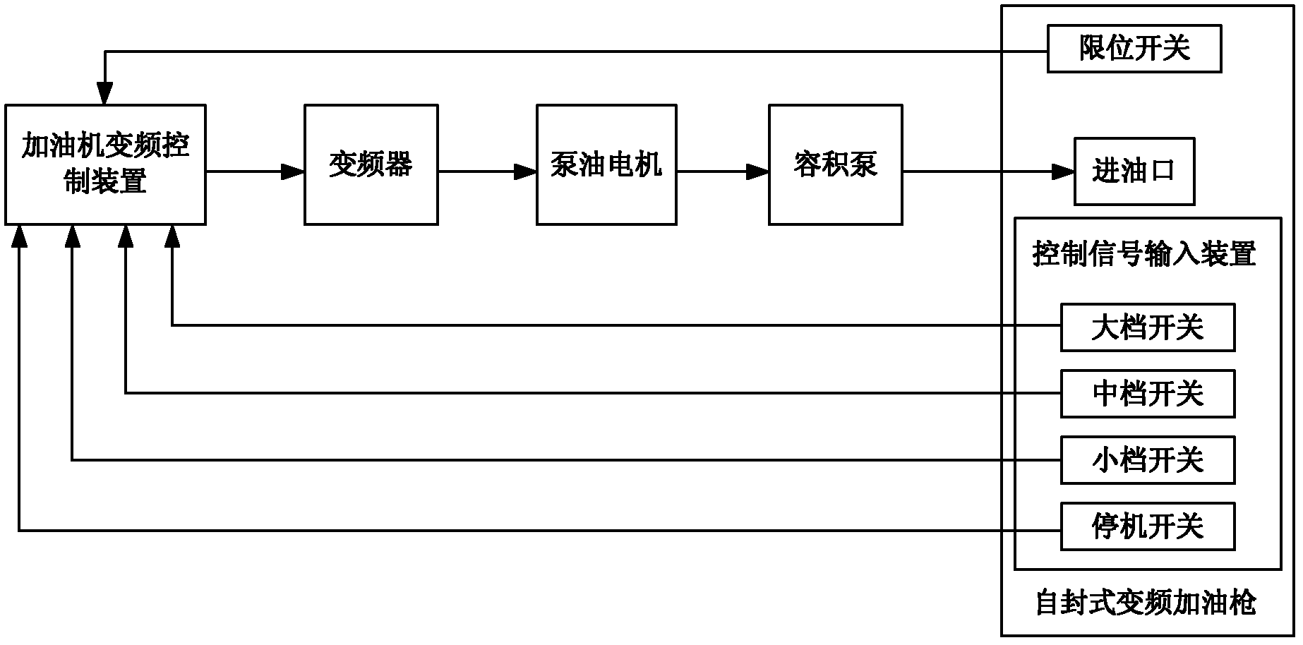
[0027] The structure of the self-styled variable frequency refueling gun of the present invention is as figure 1 and figure 2 As shown, it includes the oil inlet 1 and the self-sealing structure; the self-sealing structure is the same as that of the existing self-sealing fuel gun, and is also composed of a switch film, a self-sealing rod, a self-control rod, a steel ball, etc., and a self-sealing top cover is arranged above the switch film 4. The frequency conversion control device, frequency converter, oil pump motor and displacement pump in the hydraulic system of the fuel dispenser are connected in sequence; the positive displacement pump in the hydraulic system of the fuel dispenser is connected to the oil inlet 3 of the refueling gun to supply oil to the refueling gun. The handle 1 of the refueling gun is provided with a control signal input device 7; the control signal input device 7 includes four key switches of a high-range switch, a middle-range switch, a small-range...


PUM


Abstract

The invention discloses a self-sealing variable-frequency oil gun, which comprises an oil inlet and a self-sealing structure, wherein the self-sealing structure comprises a gating membrane; a self-sealing top cover is arranged above the self-sealing structure; a volume pump in an oiling machine hydraulic system is connected with the oil inlet of the oil gun; and an oiling machine variable-frequency control device in the oiling machine hydraulic system, a frequency converter, an oil pumping motor and the volume pump are connected in sequence. The self-sealing variable-frequency oil gun is characterized in that: the oil gun is provided with a control signal input device; the control signal input device is electrically connected with the oiling machine variable-frequency control device; a limiting switch is arranged from the self-sealing top cover to the inside of the oil gun; the top of the limiting switch is positioned on the self-sealing top cover; the bottom of the limiting switch ispressed against the top of the gating membrane; and the limiting switch is electrically connected with the variable-frequency control device. A control method of the oil gun comprises the following steps of: controlling the magnitude of the oil output of the oil gun through an input signal; and judging whether the self-sealing structure is in self-sealing state to control whether to stop the oil pumping motor. The oil gun has a good energy-saving effect and high safety performance.

Description

technical field [0001] The present invention relates to a fueling gun and its control method, more specifically, to a self-styled frequency conversion fueling gun and its control method. Background technique [0002] The conventional refueling gun used in ordinary fuel dispensers is mainly a self-styled refueling gun, and its main structure is composed of a main valve, an auxiliary valve and a self-sealing structure. The self-sealing structure is mainly composed of switch membrane, self-sealing rod, self-control rod, steel ball, etc., and a self-sealing top cover is arranged above the switch membrane. There are three steel balls on the top of the self-control rod to lock the position of the self-control rod, and it cannot be moved arbitrarily. There is a tapered self-sealing rod in the middle of the three steel balls. When no oil is added, the self-sealing rod will spread the three steel balls to make the steel ball lock the self-control rod. The top of the self-sealing ro...

Claims


Application Information

Patent Timeline
Patent Type & Authority Applications(China)
IPC IPC(8): B67D7/44B67D7/46
Inventor 刘亚俊黄佳彬唐电蒋征学
Owner SOUTH CHINA UNIV OF TECH
Why Eureka
Try Eureka