Novel water control method suitable for mine shafts

A technology for preventing and controlling water and shafts, applied in shaft equipment, drainage, mining equipment, etc., can solve problems such as shortening the service life of mines, affecting the safety of shafts, and increasing the difficulty of drainage, so as to solve water damage problems, improve construction quality, and protect mines safe effect

Active Publication Date: 2012-04-25
BLUESTAR LEHIGH ENG INST CO LTD
View PDF6 Cites 18 Cited by
  • Summary
  • Abstract
  • Description
  • Claims
  • Application Information

AI Technical Summary

Problems solved by technology

These measures are mainly used in the shaft construction process during the construction period. The above water prevention and control measures are of great significance to speed up mine construction and improve project quality; however, water leakage occurs in the production process after the shaft construction is completed, which affects the safety of the shaft and shortens the length of the mine. Service life; In addition, a large amount of water seepage enters the underground roadway or stope along the inner and outer sides of the well wall, which greatly increases the difficulty of drainage, especially the mining of soluble salt deposits poses a safety hazard

Method used


Image

  • Novel water control method suitable for mine shafts
  • Novel water control method suitable for mine shafts
  • Novel water control method suitable for mine shafts

Examples


Embodiment 1

[0021] Example 1, reference figure 1 , 2, a new water prevention method suitable for mine shafts,

[0022] (1) First, use grouting to plug water in the upper aquifer of the wellbore;

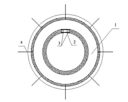
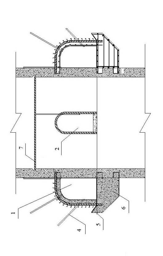
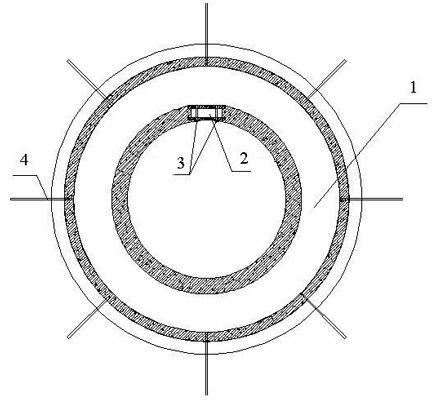
[0023] (2) A wall base 6 is provided at the junction of the aquifer and the water-resistant layer. The wall base 6 is provided with a bypass 1 for water interception. The bypass 1, the wall base 6 and the wellbore are constructed as a whole; a water discharge hole is set in the bypass 1. There is a water pipe 4 in the hole; the wall base 6 is wider than the bypass 1, and the wide part is tilted to form a water retaining 5; the bottom of the bypass 1 has a slope of 1 to 3%, and the lowest point is set at the connecting channel in the wellbore, and inorganic waterproofing Paint waterproof;

[0024] (3) A catchment circle 7 is set in the upper wellbore of the connecting road 2, and the water collected by the catchment circle 7 is discharged into the bypass 1 behind the wall;

[0025] (4) The bottom plate ...

Embodiment 2

[0026] In Example 2, the step (1) of the new water prevention method suitable for mine shafts described in Example 1 is: during the construction of the shaft, the aquifer is grouted and water shut off according to the conditions of the rock strata that the shaft passes through; When watering, first use cement slurry, or cement and sodium silicate double liquid slurry, or cement, sodium silicate and clay materials to fill the cracks in the surrounding rock, block the water outlet and isolate the water source; at the same time, cement and strengthen the mine surrounding rock to increase the stability of the shaft .

Embodiment 3

[0027] In embodiment 3, in step (2) of the new water prevention method suitable for mine shafts described in embodiment 1, the foundation of the wall base 6 is placed on a stable water-resistant layer, and the depth of the embedded water-resistant layer is controlled, Make it not penetrate the water barrier; reserve a connecting channel 2 on the shaft wall to connect the bypass 1 with the wellbore; the wall seat 6, the shaft wall and the bypass 1 support form a whole, the wall seat 6 serves as the bottom plate of the bypass 1, and the shaft wall As the inner wall of the bypass 1; the width of the wall seat 6 is 400-600mm wider than that of the bypass 1, and it is tilted on the outside to form a water retaining 5 so that the water seepage from the outer wall of the bypass 1 penetrates into the bypass 1 through the construction joint of the outer wall of the bypass 1;

[0028] The bypass 1 is supported by a steel support and reinforced concrete. A steel arch is provided every 0.4-0....


PUM


Abstract

The invention relates to a novel water control method suitable for mine shafts, which is characterized by firstly adopting grouting for water plugging at a water-bearing layer at the upper part of the shaft; arranging a wall seat at the boundary of the water-bearing layer and a water-resisting layer and arranging a bypass for water interception after the wall on the upper surface of the wall seat; arranging a dewatering orifice in the bypass and arranging a water guide pipe in the orifice, wherein the wall seat is wider than the bypass and the wide part of the wall seat is upwarped for water blocking; arranging a water collecting ring in the shaft at the upper part of an access road and draining water collected by the water collecting ring into the bypass after the wall, wherein a baseplate of the access road is 200-300mm higher than the bypass; and pre-burying a drainage pipe and enabling gushing water collected at the upper part of the bypass to self-flow into a water sump and be further drained to the ground through a drainage device. By adopting the novel water control method, the construction conditions of the mine shaft can be improved, the construction quality can be improved and the progress can be accelerated; furthermore, water damages can be effectively prevented during the production period of a mine, the safety of the mine shaft is protected, the drainage cost is reduced and the service life of the mine shaft is prolonged.

Description

Technical field [0001] The invention relates to a method for preventing and controlling water in mines, in particular to a novel method for preventing and controlling water in mine shafts. Background technique [0002] At present, the main measures to prevent water in mines in my country include ground pre-grouting, curtain grouting, working face filling grouting, and freezing construction. These measures are mainly used in the construction of the shaft during the construction period. The adoption of the above water prevention measures is of great significance to speed up the construction of the mine and improve the quality of the project; however, water leakage occurs in the production process after the completion of the shaft construction, which affects the safety of the shaft and shortens the mine. Service life; in addition, a large amount of seepage water enters the underground roadway or stope along the inner and outer sides of the shaft wall, which greatly increases the di...

Claims


Application Information

Patent Timeline
Patent Type & Authority Applications(China)
IPC IPC(8): E21D5/04E21F16/00
Inventor 张春方牛明远
Owner BLUESTAR LEHIGH ENG INST CO LTD
Why Eureka
Try Eureka