Compact type loop heat pipe device

A loop heat pipe, compact technology, applied in the field of compact loop heat pipe devices, can solve the problems of large thickness of the loop heat pipe evaporator, small transmission distance of the working medium, and inability to return the working medium, so as to shorten the transportation distance and compact structural design , Improve the effect of heat transfer performance

Active Publication Date: 2012-04-25
CHINA ELECTRONIC TECH GRP CORP NO 38 RES INST
View PDF8 Cites 9 Cited by
  • Summary
  • Abstract
  • Description
  • Claims
  • Application Information

AI Technical Summary

Problems solved by technology

Chinese patent CN200820123488.7 "A loop heat pipe cooling device" discloses another loop heat pipe structure of a flat plate evaporator. In this flat plate evaporator, the compensation chamber is located in the height direction of the steam channel, and the liquid working medium It is directly transported to the evaporation area through the capillary action of the porous structure, the transmission distance of the working medium is small, and the fl

Method used


Image

  • Compact type loop heat pipe device
  • Compact type loop heat pipe device
  • Compact type loop heat pipe device

Examples


Embodiment Construction

[0020] The content of the present invention will be described below in conjunction with specific embodiments.

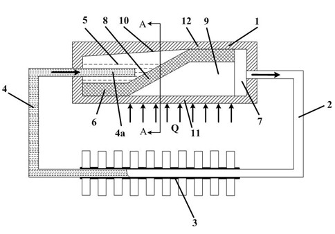
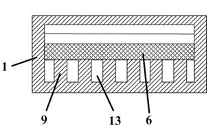
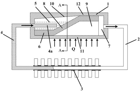
[0021] Such as figure 1 Shown is a schematic structural view of the compact loop heat pipe device of the present invention, figure 2 for figure 1 A-A sectional view in . The compact loop heat pipe device of the present invention includes an evaporation part 1, a gas phase pipeline 2, a condensation part 3 and a liquid phase pipeline 4, and constitutes a closed circulation channel. One end of the evaporator 1 is connected with a liquid phase pipeline 4 , and the other end is connected with a gas phase pipeline 2 . The airtight circulation channel is filled with working medium in gas phase or liquid phase.

[0022] The evaporating part 1 is in the shape of a plate, the plate side close to the condensing part 3 is a heating surface 11 , and the plate side away from the condensing part 3 is a non-heating surface 12 . A compensation chamber 5 , a capillary structure...


PUM


Abstract

The invention relates to a compact type loop heat pipe device which comprises an evaporation part, a gas phase pipeline, a condensation part and a liquid phase pipeline. The gas phase pipeline and the liquid phase pipeline are communicated, and further, form a closed circulation passage; a compensation chamber, a capillary structure, a vapor chamber and a support wall are arranged inside the evaporation part; the capillary structure is clung to the heating surface and is extended from an end part of the compensation chamber to a non-heating surface along the flowing direction of a working medium in the evaporation part; a compensation chamber section of the capillary structure, which is clung to the inner wall of the compensation chamber, and a non-heating section of the capillary structure, which is clung to the non-heating surface, are connected together through an obliquely-arranged oblique section; the compensation chamber is communicated with the liquid phase pipeline; and the vapor chamber is communicated with the gas phase pipeline. According to the compact type loop heat pipe device, the heat-dissipating efficiency is increased through changing the placement manner of the capillary structure, so that the evaporation area per unit length is larger, the structure of the loop heat pipe device is designed to be more compact, the normal work under various arrangement conditions can be realized, and the compact type loop heat pipe device has excellent anti-gravity performance.

Description

technical field [0001] The invention relates to a cooling device for electronic components, in particular to a compact loop heat pipe device for cooling components in a narrow space. Background technique [0002] With the development of microelectronics technology and the continuous improvement of chip integration, the calorific value of electronic components increases accordingly, and the heat flux density increases accordingly. The thermal management of electronic devices is one of the key technologies restricting its development. In addition, with the improvement of the integration of electronic components, the space of the electronic device is also more compact, which puts forward higher requirements on the heat transport capacity and heat transfer efficiency of the heat sink. [0003] Loop heat pipe device, as an extension of ordinary heat pipe technology, relies on the phase change of liquid working medium to achieve heat dissipation. It has the characteristics of str...

Claims


Application Information

Patent Timeline
IPC IPC(8): F28D15/04H01L23/427
CPCH01L2924/0002H01L2924/00
Inventor 张先锋张根烜
Owner CHINA ELECTRONIC TECH GRP CORP NO 38 RES INST
Why Eureka
Try Eureka