Micro-raman spectrum experiment apparatus for adjustable polarization direction continuous collaboration/covariation

A technology of polarization direction and micro-Raman, which is applied in the field of optical measurement, can solve the problems that affect the accuracy and life, cannot be realized, and the operation is cumbersome, and achieve the effect of small intensity loss

Active Publication Date: 2012-04-25
TIANJIN UNIV
View PDF3 Cites 15 Cited by
  • Summary
  • Abstract
  • Description
  • Claims
  • Application Information

AI Technical Summary

Problems solved by technology

Although this method of separate control provides more choices of polarization configurations, it is quite cumbersome for experiments that need to adjust the polarization directions of incoming and scattered light at any time, and it is impossible to adjust the polarization directions continuously, synergistically, or at any angle.
At the same time, the shell of the spectrometer host must be opened to adjust the polarization direction of the scattered light, so repeated operations are likely to bring dust or other debris into the spectrometer, thereby affecting its accuracy and life
The published technologies related to the continuous cooperative adjustment method and device of the Raman spectroscopy experimental system can only realize the coordinated adjustment of incident and scattered polarization, but cannot achieve synergistic adjustment.

Method used


Image

  • Micro-raman spectrum experiment apparatus for adjustable polarization direction continuous collaboration/covariation
  • Micro-raman spectrum experiment apparatus for adjustable polarization direction continuous collaboration/covariation
  • Micro-raman spectrum experiment apparatus for adjustable polarization direction continuous collaboration/covariation

Examples


Embodiment Construction

[0018] The present invention will be further described below in conjunction with the accompanying drawings and through specific embodiments. It should be noted that this embodiment is illustrative rather than restrictive, and does not limit the protection scope of the present invention.

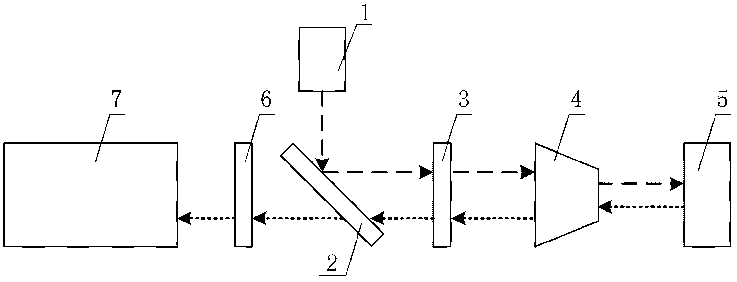
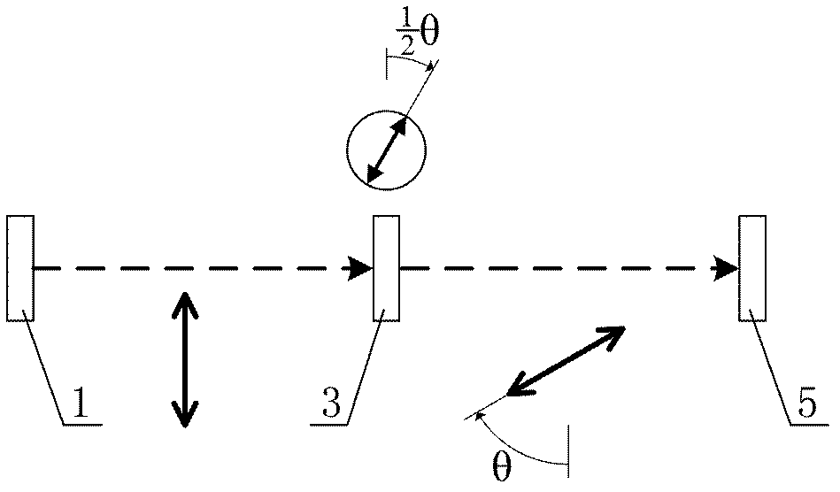
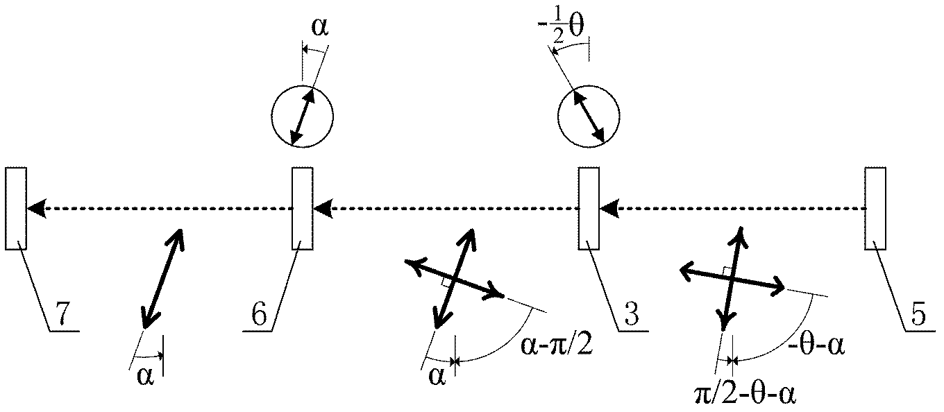
[0019] Micro-Raman spectroscopy experimental device with continuous coordination of polarization direction and adjustable synergy difference. In terms of optical path construction and connection: it consists of laser 1, Edge filter 2, microscope 4 and Raman spectrograph 7. Micro-Raman Spectrum Experimental System. A half-wave plate 3 is provided between the Edge filter 2 and the microscope 4; a polarizer 6 is provided between the Edge filter 2 and the Raman spectrograph 7, and the polarization is formed by the half-wave plate 3 and the polarizer 6 Coordinative or polarization coordinating components. The laser light emitted by the laser 1 is reflected by the Edge filter 2, transmitted by th...


PUM


Abstract

The invention discloses a micro-raman spectrum experiment apparatus for adjustable polarization direction continuous collaboration/covariation. A micro-raman spectrum system is composed of a laser machine, an Edge optical filter, a microscope and a Raman spectrograph, a polarization collaboration/covariation adjusting module is composed of a half-wave plate and a polaroid sheet. The laser emitted by the laser machine is performed Edge optical filter reflection, half-wave plate transmission and microscope focusing incidence on the surface of the measured object. The diffusion light collected by the microscope transmits through the half-wave plate, the Edge optical filter and the polaroid sheet and then enters in the Raman spectrograph for photorecording the spectrum information. By setting the vibration detection angle of the polaroid sheet as zero or nonzero value-alpha, the fast optical axis angle of the half-wave plate is adjusted to be half of the rotation angle in the polarization direction, so that collaboration regulation or alpha angle covariation regulation of polarization direction of incidence light and scattered light can be realized. On the basis of unchanged functions and precision of the traditional micro-raman spectrum experiment system, the modularization and simplification of controlling polarization collaboration/covariation can be realized, and the manufacture cost can be reduced.

Description

technical field [0001] The invention belongs to the optical measurement technology, and in particular relates to a micro-Raman spectrum experimental device capable of continuously synergizing and synergistically adjusting the polarization directions of incident light and scattered light. Background technique [0002] The micro-Raman spectroscopy experimental system generally uses visible, ultraviolet or near-infrared lasers as the excitation light source, and uses the good polarization of the laser to analyze the Raman scattering characteristics of the research object under various combinations of incident light and scattered light polarization directions. It is an important application mode of the micro-Raman spectroscopy experimental system. With the continuous deepening of scientific research and engineering applications, measurement tasks such as quantitative measurement of polarization Raman parameters of crystal materials, estimation of orientation of fiber composite m...

Claims


Application Information

Patent Timeline
Patent Type & Authority Applications(China)
IPC IPC(8): G01N21/65G01N21/01G02B27/28
Inventor 仇巍亢一澜李秋雷振坤邓卫林
Owner TIANJIN UNIV
Why Eureka
Try Eureka