
Direct current power supply system contactor adhesion detection apparatus, method and electric vehicle thereof

A technology of power supply system and detection method, which is applied in the direction of measuring device, instrument, measuring electricity, etc., can solve the problems of random error at both ends of the contact, high specification, single source of supply, etc., and achieves low precision requirements, simple structure, and convenient implementation. Effect

Inactive Publication Date: 2012-04-25
TIANJIN SANTROLL ELECTRIC AUTOMOBILE TECH CO LTD
View PDF6 Cites 28 Cited by
  • Summary
  • Abstract
  • Description
  • Claims
  • Application Information

AI Technical Summary

Problems solved by technology

[0003] At present, the micro switch attached to the main contactor itself is generally used for adhesion detection. This method has the following defects: there are relatively few types of main contactors to choose from, the source of goods is single, and the specifications are relatively high, and the cost is high; the peripheral circuit wiring is complicated, which reduces the System reliability; additional MCU interface and supporting circuits need to be occupied
[0004] Another method that is often used is to detect the adhesion by detecting the voltage at both ends of the main contactor contact. For a low-voltage system with a controllable pre-charging circuit, it can only be carried out before the system capacitor bank is not charged, and real-time detection cannot be achieved. ; For the low-voltage system with non-controllable pre-charging circuit, the pre-charging of the capacitor bank may be completed during the adhesion detection. The reasons for the error of the put and voltage divider resistance will introduce additional random errors to the sampling circuit at both ends of the contact, and then in mass production, a large number of unqualified products will be produced
If high-precision components are used, it will increase the unnecessary cost of the system and achieve little effect

Method used


Image

  • Direct current power supply system contactor adhesion detection apparatus, method and electric vehicle thereof
  • Direct current power supply system contactor adhesion detection apparatus, method and electric vehicle thereof
  • Direct current power supply system contactor adhesion detection apparatus, method and electric vehicle thereof

Examples


Embodiment Construction

[0028] The present invention will be further described below in conjunction with the drawings:

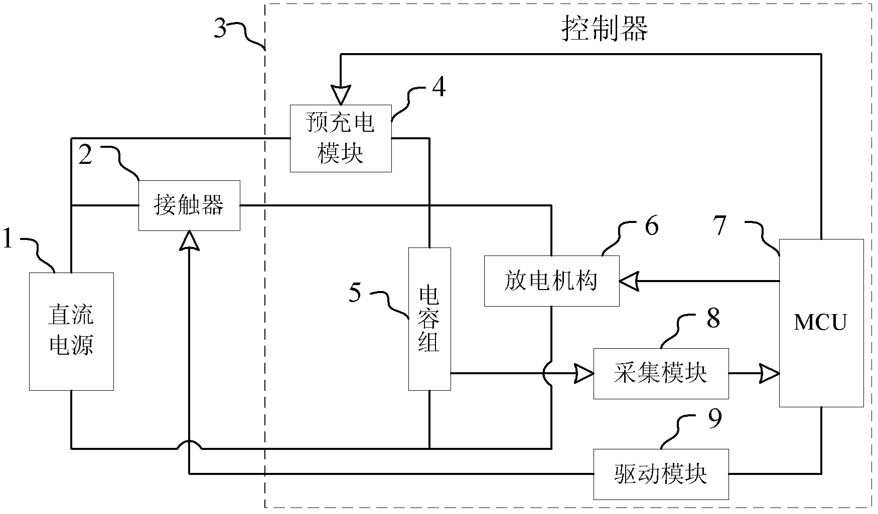
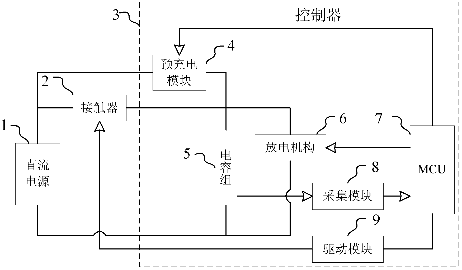
[0029] As attached figure 1 , 1 is a DC power supply, 2 is a contactor, 3 is a controller, 4 is a pre-charge module, 5 is a capacitor bank, 6 is a discharge mechanism, 7 is an MCU, 8 is an acquisition module, and 9 is a drive module.

[0030] A contactor adhesion detection device for a DC power supply system in this embodiment includes: a DC power supply 1, a contactor 2 connected to the DC power supply 1 and electrical equipment, and a controller 3, the controller 3 is used to drive and control the electrical equipment, The controller 3 includes a capacitor bank 5 connected to the DC power supply 1 through a contactor 2, a pre-charging module 4 connected to the DC power supply 1 and the capacitor bank 5, a drive module 9 for driving the contactor, and collection of information on the capacitor bank. The module 8 and the main control module MCU7, the controller 3 also includes a dischar...


PUM


Abstract

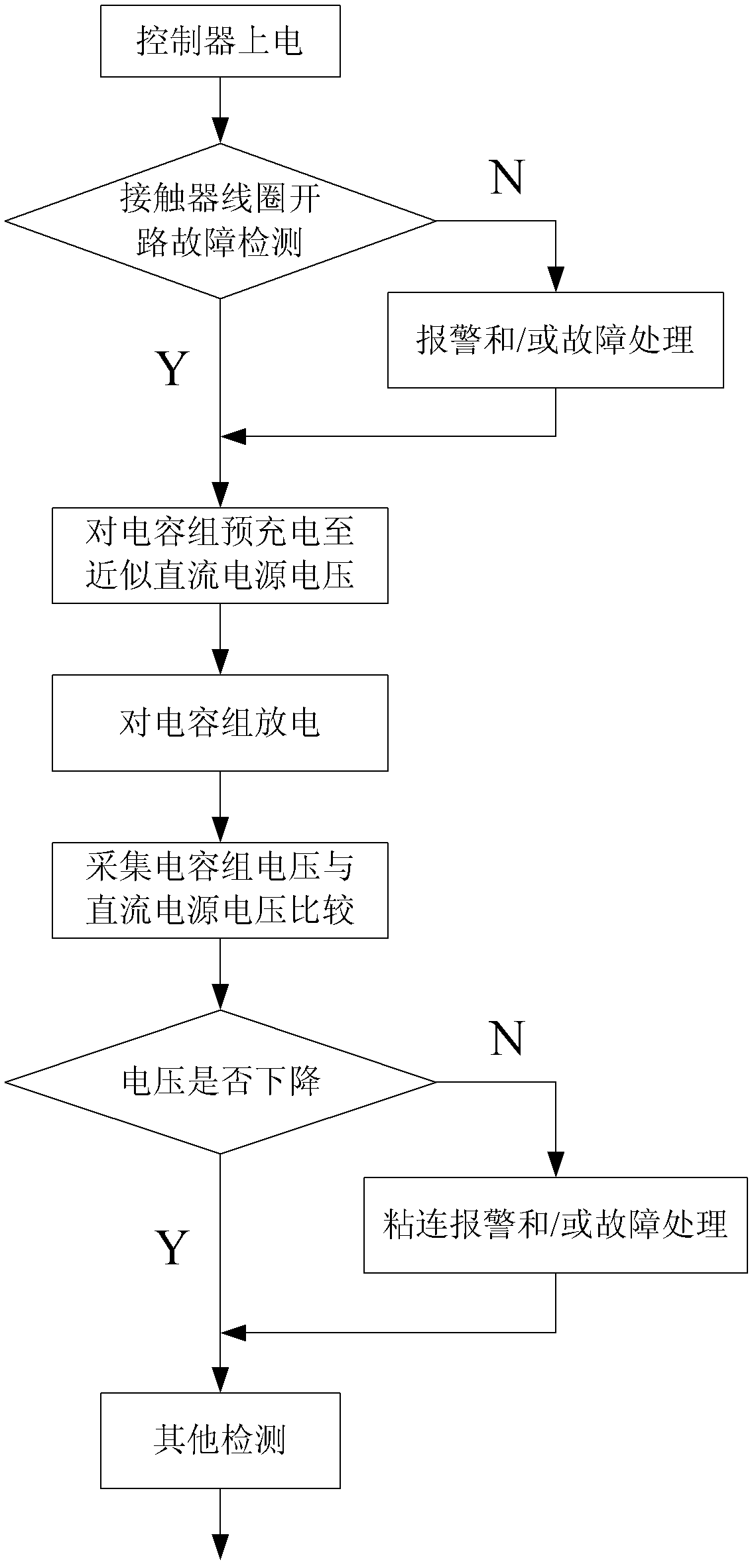
Aiming at a problem existed in the current method for solving contactor contact adhesion, the invention provides a direct current power supply system contactor adhesion detection apparatus and a detection method with higher precision and a stronger applicability and an electric vehicle which uses the apparatus and / or the method. Through using a precharging module and a capacitor pack in a power-driven controller in a system applied by the contactor, charging and discharging and voltage detection is performed to the capacitor pack which is connected with the direct current power supply through the contactor. A detection result is compared so as to realize the contactor adhesion detection. Equipment damage and even personnel injury caused by the contactor adhesion can be avoided. Reliability of the contactor application system can be increased.

Description

Technical field [0001] The invention relates to the technical field of electric vehicles, and in particular to a method for detecting adhesion of contactors of a DC power supply system and an electric vehicle. Background technique [0002] In electric vehicles, the contactor plays the role of connecting or disconnecting the DC power supply and the electrical equipment. When it is connected or disconnected, the DC contactor contact adhesion failure may occur, so that the contactor contact cannot be disconnected. Threaten the safety of drivers and the overall vehicle. [0003] At present, the micro switch attached to the main contactor is generally used for adhesion detection. This method has the following disadvantages: there are fewer types of main contactors that can be selected, a single source of supply, high specifications, and high costs; the peripheral circuit wiring is complicated, which reduces The reliability of the system; additional MCU interfaces and supporting circuit...

Claims


Application Information

Patent Timeline
IPC IPC(8): G01R31/02
Inventor 孙彦军陈华财
Owner TIANJIN SANTROLL ELECTRIC AUTOMOBILE TECH CO LTD
Learn More