Precise filter

A precision filter and filter element technology, which is applied in fixed filter element filters, filtration separation, chemical instruments and methods, etc., can solve the problems of difficulty in adoption, short-circuit leakage of filtration, and small space, etc., to achieve convenient installation, ensure filtration effect, simple structure

Inactive Publication Date: 2012-05-02
CHANGZHOU CONNECT MACHINERY EQUIP
View PDF7 Cites 14 Cited by
  • Summary
  • Abstract
  • Description
  • Claims
  • Application Information

AI Technical Summary

Problems solved by technology

It can be seen from this: (1) when replacing the filter element 2, the head 6 needs to be opened first, and the upper part of the precision filter needs to leave an operating space equal to the filter element 2, so that the filter element 2 can be removed from the top of the cylinder body 4 Not only is it inconvenient to replace, but also it is difficult to meet the requirements of using on board due to the small and limited space in the cabin.
(2) When installing the filter element 2, since the cylinder body 4 is relatively high, and it is from the top down, it is impossible to fully confirm whether the filter element 2 is installed in place, which can easily cause short-circuit leakage during filtration
(3) As a precision filter for filtering seawater, the anticorrosion of materials is very important. The anticorrosion technology of inner wall coating is not easy to adopt in this structure, because the part below the water baffle 3 of the cylinder 4 is a non-open structure, and the inner wall When painting, there is no guarantee that the painting is complete and free of defects, leaving hidden dangers to the normal use of the equipment

Method used


Image

  • Precise filter
  • Precise filter
  • Precise filter

Examples


Embodiment 1)

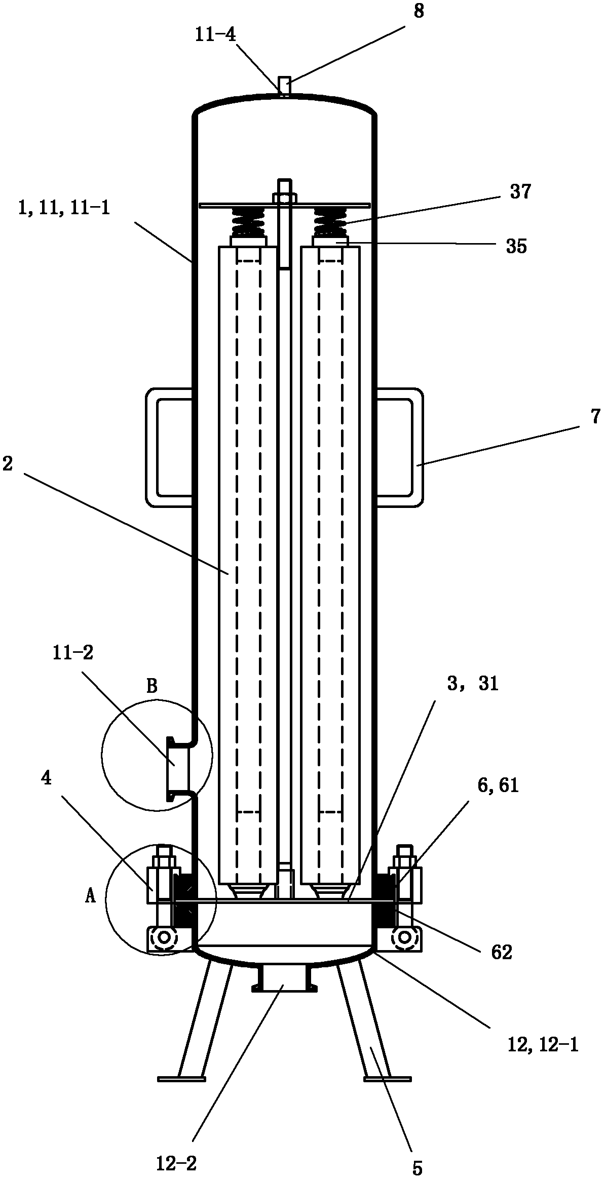
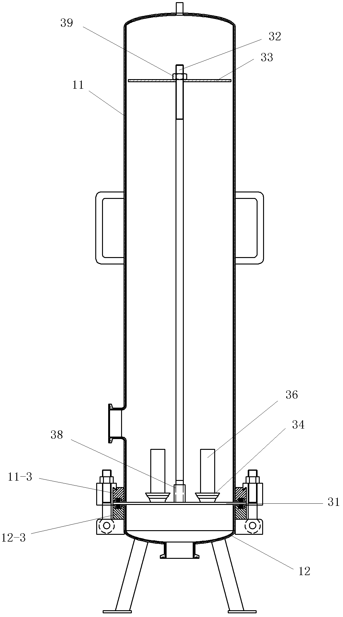
[0052] See figure 1 , The precision filter of this embodiment is composed of a cylinder body 1, a filter element 2, a filter element mounting frame 3, a connector 4, a support column 5, a sealing ring 6, a handle 7 and an exhaust valve 8. The filter element 2 is installed on the filter element mounting frame 3 , the filter element mounting frame 3 is arranged in the cylinder body 1 , and the support column 5 is arranged on the bottom of the cylinder body 1 .

[0053] See figure 1 with Figure 5 , the cylinder body 1 includes a main cylinder body 11 located at the upper part and a lower cylinder body 12 located at the lower part. The main cylinder body 11 and the lower cylinder body 12 are detachably and hermetically fixedly connected by corresponding connecting pieces 4 .

[0054] See figure 1 with Figure 5 , the main cylinder 11 is a cylindrical shell with a top cover opening downward. The main cylinder 11 includes a metal cylinder 11a and a corrosion-resistant coating...


PUM

PropertyMeasurementUnit
thicknessaaaaaaaaaa
thicknessaaaaaaaaaa

Abstract

The invention discloses a precise filter which comprises a cylinder, 2-8 filter elements, a filter element installing frame and connectors, wherein all the filter elements and the filter element installing frame are arranged in the cylinder, the filter element installing frame is fixedly connected with the cylinder, and all the filter elements are fixedly connected with the filter element installing frame. The precise filter is characterized in that the cylinder comprises a main cylinder at the upper part of the cylinder and a lower cylinder at the lower part of the cylinder, the filter element installing frame comprises a separator, a pull rod, a pressing plate, filter element lower seats, a filter element pressing seat, a compression spring and a gland nut, the end port of each filter element lower seat is respectively welded to a corresponding through hole of the separator hermetically so that the cavity of the filter element lower seat is communicated with a space at the lower side of the separator, each corresponding filter element, the filter element pressing seat and the compression spring are arranged between the filter element lower seats and the pressing plate in sequence from bottom to top, the edge part of the separator of the filter element installing frame is clamped between the lower end face of the main cylinder and the upper end face of the lower cylinder, and the separator of the filter element installing frame, the main cylinder and the lower cylinder are detachably, fixedly and hermetically connected into a whole through the connectors.

Description

technical field [0001] The invention relates to a reverse osmosis seawater desalination device, in particular to a precision filter for a marine reverse osmosis seawater desalination device. Background technique [0002] The basic process of marine reverse osmosis seawater desalination is as follows: seawater enters the multi-media filter from the water supply pump for filtration, and then enters the precision filter and security filter for filtration. The filtered low-pressure seawater enters the high-pressure pump to pressurize one way, and the other Enter the pressure exchange type energy recovery device to boost the pressure. The boosted seawater is pressurized by the booster pump and mixed with the high-pressure pump water to enter the reverse osmosis membrane stack system. After the treatment of the reverse osmosis membrane stack system, part of the seawater passes through the reverse osmosis membrane. After the fresh water is formed, it enters the fresh water tank for...

Claims


Application Information

Patent Timeline
Patent Type & Authority Applications(China)
IPC IPC(8): B01D29/52
Inventor 周一
Owner CHANGZHOU CONNECT MACHINERY EQUIP
Why Eureka
Try Eureka