Vertical/horizontal automatic squeezer

A pressing machine and automatic technology, applied in the direction of presses, manufacturing tools, etc., can solve the problems of low efficiency, high energy consumption, high moisture content, etc., and achieve the effect of high efficiency, low energy consumption, and high production efficiency

Inactive Publication Date: 2012-05-02
柳大海
View PDF9 Cites 18 Cited by
  • Summary
  • Abstract
  • Description
  • Claims
  • Application Information

AI Technical Summary

Problems solved by technology

The principle of the existing pulping machine is to use high-pressure water to squeeze the slurry into the storage space of the filter device. This water-squeezing method not only has a high water content, but also consumes a lot of energy and has low efficiency. Its output per hour About 2 cubic meters, the moisture content is about 10%, and it needs to consume at least 6 degrees of electricity

Method used


Image

  • Vertical/horizontal automatic squeezer
  • Vertical/horizontal automatic squeezer
  • Vertical/horizontal automatic squeezer

Examples


Embodiment 1

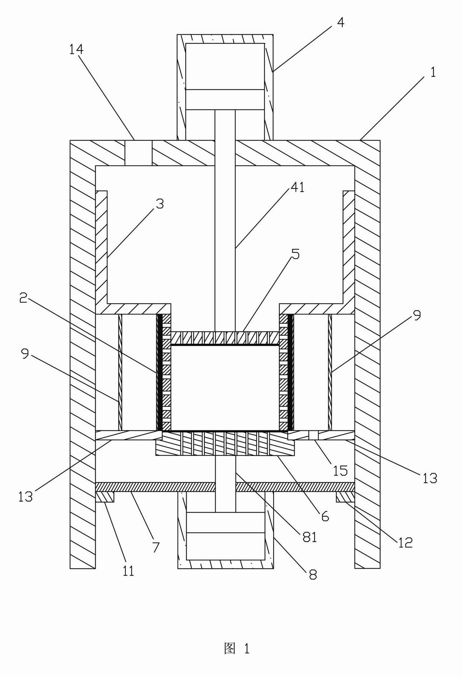
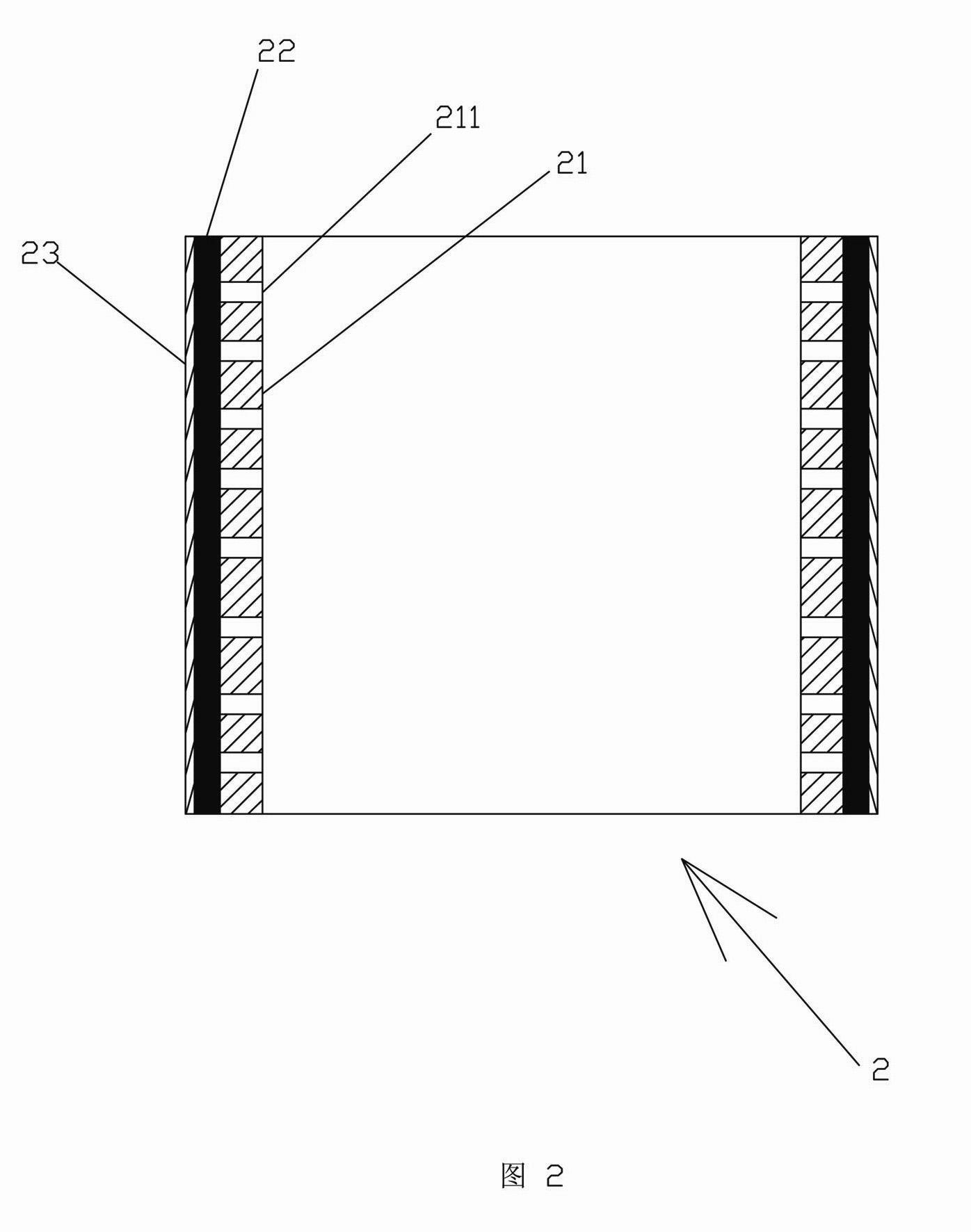
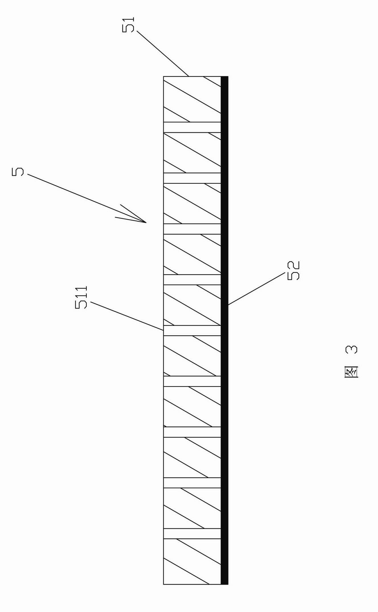
[0030] refer to figure 1 , a vertical automatic press, which includes a vertical frame 1, a press barrel 2 that is straight up and down (that is, both upper and lower ends are open), a slurry barrel 3, an upper hydraulic cylinder 4, a pressure plate 5, and a movable plug Disc 6, horizontal mounting frame 7 and lower hydraulic cylinder 8. The bottom of the vertical frame 1 is provided with two horizontal slide rails 11, 12, and the middle part of the vertical frame 1 is fixed with a horizontal plate 13. The horizontal mounting frame 7 is installed on the slide rails 11, 12, and it can move horizontally on the slide rails 11, 12; The end of the piston rod 81, and the movable blocking plate 6 can move and block the lower end of the squeeze barrel 2, while referring to image 3 The above-mentioned movable blocking plate 6 is composed of a blocking plate body 61 with a stepped surface and a blocking plate filter layer 62 fixed on the upper surface of the blocking plate body 61. T...

Embodiment 2

[0034] refer to Figure 5 , Figure 7 and Figure 8, a horizontal automatic press, which includes a horizontal frame 1', a press barrel 2' that is straight from left to right (that is, both ends of the left and right are open), a total hydraulic cylinder 3', a pressure plate 5', left and right Two movable blocking plates 61', 62', and left hydraulic cylinders 71', 72' and right hydraulic cylinders 73'. The platen 5' is composed of a platen body 51' and platen filter layers 52', 53' fixed on the left and right surfaces of the platen body 51' at the same time. The platen body 51' is evenly distributed with through holes 511', these The diameter of the through hole 511' is between 1-3 cm. In addition, in order to enhance the sealing performance, it is usually necessary to wrap a sealing ring (not shown in the figure) on the side wall of the pressure plate body 51'. The above-mentioned left and right movable blocking plates 61', 62' are composed of a blocking plate body 63' wit...


PUM


Abstract

The invention discloses a vertical automatic squeezer which comprises a vertical frame, an up-and-down through squeezing barrel, a pulp barrel, an upper hydrocylinder of which the piston rod can extend into the squeezing barrel, a platen and a mobile blocking disk, wherein the platen compresses the squeezing barrel to obtain a dry matter. The vertical automatic squeezer has the advantages of high production efficiency, low energy consumption and low water content of the dry matter. The invention also discloses a horizontal automatic squeezer which comprises a horizontal frame, a left-and-right through squeezing barrel, a general hydrocylinder, a platen, a left feed plate, a right feed plate, a left mobile blocking disk, a right mobile blocking disk, a left hydrocylinder and a right hydrocylinder, wherein the left and right mobile blocking disks respectively penetrate through the middle parts of the feed plates. The horizontal squeezer not only has the advantages in the vertical squeezer, but also has the advantage of higher production efficiency.

Description

technical field [0001] The invention relates to a grouting equipment capable of realizing mud-water separation, in particular to an automatic squeezer for various stone pulps. Background technique [0002] Pressing machinery is mainly divided into squeezer and pulper. The effect of the pulper is not ideal, usually with a moisture content of 20%. The principle of the existing squeezer is to use high-pressure water to squeeze the slurry into the storage space of the filter device. This way of squeezing the slurry with water not only has a high water content, but also consumes a lot of energy and has low efficiency. Its output per hour About 2 cubic meters, the moisture content is about 10%, and it needs to consume at least 6 kilowatt-hours of electricity. Contents of the invention [0003] The present invention provides a vertical automatic press, the purpose of which is to overcome the defects of low production efficiency, high moisture content and serious energy consumpti...

Claims


Application Information

Patent Timeline
Patent Type & Authority Applications(China)
IPC IPC(8): B30B9/06
Inventor 李仁祯陈小兵
Owner 柳大海
Why Eureka
Try Eureka