Internal-combustion permanent-magnet linear power generation device

A permanent magnet linear and power generation device technology, applied in the direction of electromechanical devices, electrical components, machines/engines, etc., can solve the problems of low power density, high power density, difficulty in ensuring manufacturing accuracy and long-term reliability, and avoid lead wire movement Effect

Active Publication Date: 2013-09-18
NINGBO INST OF MATERIALS TECH & ENG CHINESE ACADEMY OF SCI
View PDF4 Cites 4 Cited by
  • Summary
  • Abstract
  • Description
  • Claims
  • Application Information

AI Technical Summary

Problems solved by technology

The moving coil structure generally adopts an ironless winding structure. The advantage is that the mover is mainly composed of coils and electrical insulating materials, and there is no iron loss, but the power density is relatively low, and there are problems with lead wire movement.
The moving magnet structure does not have the problem of lead wire movement, and usually has a higher thrust density, but the temperature of the combustion chamber rises sharply during the process of combustion and expansion, which causes the temperature of the piston to rise and transfer heat to the permanent magnet of the mover, resulting in a permanent magnet. The magnetic performance of the magnet decreases or even loses its magnetism due to heating, and the quality, thrust fluctuation and eddy current loss of the permanent magnet mover are relatively large
[0004] In addition, the above-mentioned two-stroke free-piston engine can provide greater power under the same working volume and weight conditions, so the power density is relatively high, but its energy-saving and environmental protection performance is relatively poor
Some researchers proposed that the four-stroke free-piston internal combustion linear power generation system has certain advantages in terms of energy saving and environmental protection performance, but the power density is relatively low, and the number of working cycles at the same operating frequency is only two strokes. 50% of
[0005] In addition, in order to improve the power density and efficiency of internal combustion linear generators, some researchers have proposed the use of Halbach permanent magnet arrays, but radially magnetized magnetic rings generally use a combination of multi-piece magnetic rings, the manufacturing and assembly process is complicated, and the manufacturing accuracy and long-term reliability Difficult to guarantee, and the cost is high

Method used


Image

  • Internal-combustion permanent-magnet linear power generation device
  • Internal-combustion permanent-magnet linear power generation device

Examples


Embodiment Construction

[0020] The present invention will be further described below in conjunction with the accompanying drawings and embodiments.

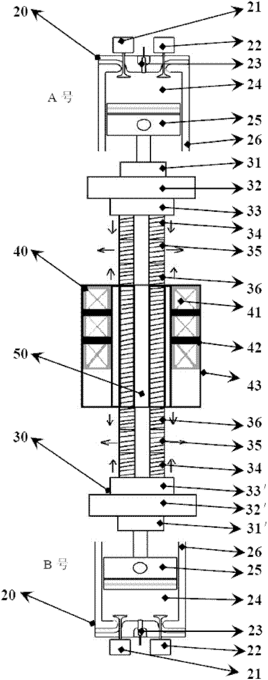
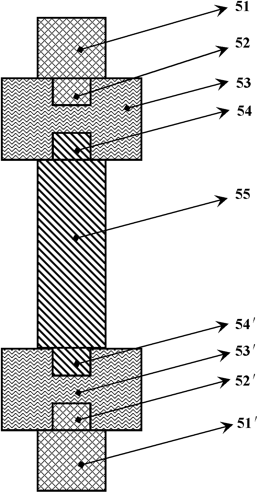
[0021] figure 1 It is a structural schematic diagram of an embodiment of the internal combustion permanent magnet linear power generation device of the present invention, figure 2 yes figure 1 The schematic diagram of the structure of the moving rod used in the embodiment, where the reference signs are:

[0022] Two-stroke internal combustion chamber 20, permanent magnet mover 30, coil stator 40, moving rod 50, electromagnetic valve 21, electromagnetic valve 22, igniter 23, combustion chamber 24, piston 25, box body 26, first compression nut 31, The second compression nut 31', the first group of heat dissipation rings 32, the second group of heat dissipation rings 32', the first group of heat insulation rings 33, the second group of heat insulation rings 33', the axially magnetized permanent magnet rings 34, the diameter Directly magnetized permanen...


PUM


Abstract

The invention discloses an internal-combustion permanent-magnet linear power generation device, which comprises two two-stroke internal-combustion chambers with the same structure and a permanent-magnet linear power generator including a coil stator, a movable rod and a permanent-magnet rotor sleeved on the movable rod in coaxial mode. The permanent-magnet rotor comprises two groups of radiating rings, two groups of heat insulation rings and a magnetizing permanent-magnet ring group. Correspondingly, the movable rod comprises two movable rod heat transmission sections, a heat insulation section and a movable rod permanent-magnet section. The internal-combustion permanent-magnet linear power generation device can quickly transmit a lot of heat generated in combustion expansion acting processes to the movable rod heat transmission sections through a piston to radiate the heat quickly through the movable rod heat transmission sections and the radiating ring group. Simultaneously, the heat is insulated by the movable rod heat insulation section and the heat insulation ring groups. The movable rod permanent-magnet section and the permanent-magnet ring group sleeved on the movable rod permanent-magnet section are prevented from being affected by heat and keep magnetism. Therefore, the problem that the magnetism of a permanent-magnet body can be reduced and even lost due to the fact that heat is transmitted by the piston of an existing internal-combustion permanent-magnet linear power generation device to the permanent-magnet body and the permanent-magnet body is heated is resolved.

Description

technical field [0001] The invention relates to a free piston engine, in particular to an internal combustion permanent magnet linear power generation device. Background technique [0002] Since the free piston engine appeared in the 1920s, it has developed rapidly. But in the early 1960s, the free-piston engine failed miserably in the competition with the crankshaft internal combustion engine and gradually withdrew from the stage. But the unique structure of the free-piston engine has been widely accepted by the engineering community, and has laid the foundation for the further development of free-piston technology in the future. By the 1990s, with the rapid development of permanent magnet linear motor technology, a free-piston internal combustion linear generator appeared. This technology uses a permanent magnet linear generator as a linear load for a free piston internal combustion engine, and fuel The chemical energy is converted into linear motion mechanical energy, a...

Claims


Application Information

Patent Timeline
Patent Type & Authority Patents(China)
IPC IPC(8): F02B71/04H02K35/02
Inventor 黄彬彬廖有用张杰章达众周杰陆彤舒鑫东
Owner NINGBO INST OF MATERIALS TECH & ENG CHINESE ACADEMY OF SCI
Why Eureka
Try Eureka