High-power non-inductive wire-wound resistor

A wire-wound resistor and high-power technology, which is applied in the field of high-power non-inductive wire-wound resistors, can solve the problems of complex winding process, and achieve the effects of good heat dissipation, low production cost, and easy installation.

Active Publication Date: 2012-05-02
江苏嘉诚中贝能源科技有限公司
View PDF2 Cites 4 Cited by
  • Summary
  • Abstract
  • Description
  • Claims
  • Application Information

AI Technical Summary

Problems solved by technology

[0004] Wire-wound resistors are structures in which resistance wires are wound on an insulating carriage. The resistance wires generally have relatively high resistivity alloy resistance wires. The insulating skeleton is made of ceramics, plastics, and metal materials coated with insulation. One or more layers of resistance can be wound on the skeleton according to the requirements, or the non-inductive winding method is used. The non-inductive winding method usually adopts winding methods such as inter-winding, split winding, and double-wire parallel winding. The winding process is relatively complex

Method used


Image

  • High-power non-inductive wire-wound resistor
  • High-power non-inductive wire-wound resistor
  • High-power non-inductive wire-wound resistor

Examples


Embodiment 1

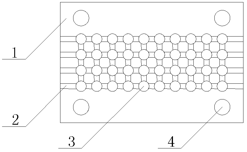
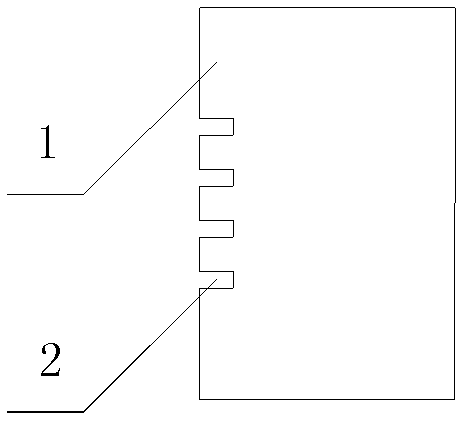
[0034] In this embodiment, the skeleton is made of porcelain material, and the basic skeleton size is 70mm×46mm×12.5mm, in which the threading hole matrix is ​​4×10, the threading hole diameter is Φ4mm, the wire groove size is 2mm×4mm, and the installation hole is Φ6mm ;

[0035] The size of the auxiliary porcelain tube is Φ5mm×10mm;

[0036] Among them, the resistance value of the non-inductive high-power fixed resistor is taken as R=11.4186Ω, the resistivity of a single resistance wire is ρ=0.6Ω / m, and the wire diameter of the resistance wire is 1.0mm 2 , utilize formula (1) to calculate resistance wire length L=18m;

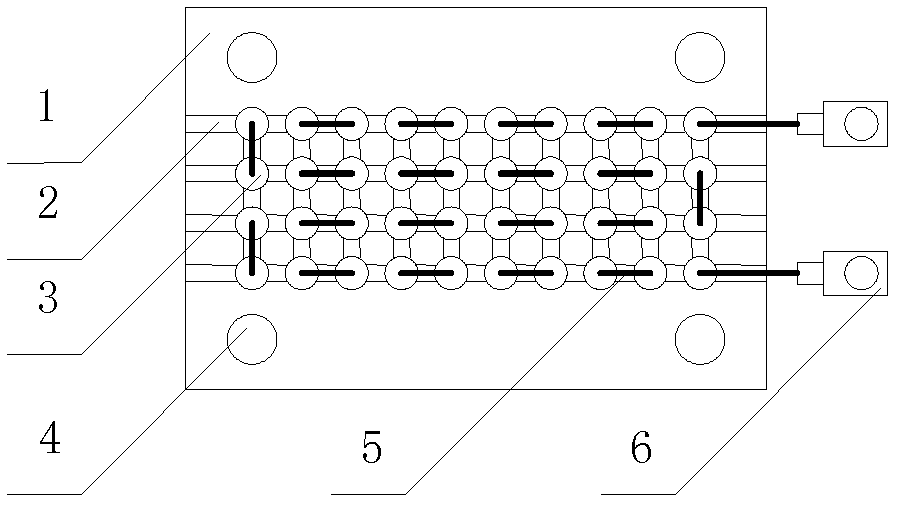
[0037] The connection between the resistance wire and the skeleton is realized by the single-wire parallel winding method, such as Figure 3 ~ Figure 5 As shown, the specific method is: connect one end of the resistance wire to the first terminal, use the last hole in the first line of the threading hole array as the initial threading hole, pass the other en...

Embodiment 2

[0041] Another present implementation of the present invention is to apply the wirewound resistor in the BKMJ-JL-Y type passive filter device, and the specific operation is as follows:

[0042] The mounting screw fixes the high-power non-inductive wirewound resistor of the present invention on the bracket of the filter device through the mounting hole, so that the threading hole of the resistor remains vertical. Since the threading hole diameter of the skeleton is larger than the resistance wire diameter, an air duct is formed. , the heat generated by high-power non-inductive wire-wound resistors can be dissipated by air convection. Therefore, an axial fan can be installed under the frame for forced ventilation to increase the rated power of the resistor. The specific method is:

[0043]The model of the axial flow fan is 100FZYZ-5, the distance between the four installation holes is 90X90, the diameter of the axial flow fan installation holes is 6mm, the spacing standard and di...


PUM

PropertyMeasurementUnit
Sizeaaaaaaaaaa
Wire diameteraaaaaaaaaa
Lengthaaaaaaaaaa

Abstract

The invention relates to a high-power non-inductive wire-wound resistor, belonging to the field of a resistor in basic electrical component. The high-power non-inductive wire-wound resistor comprises a plurality of frameworks and resistance wires, wherein each framework comprises a mounting hole, a threading hole and a lead groove; and the resistance wires can be connected with the frameworks by a single-wire parallel winding method. The high-power non-inductive wire-wound resistor has the advantages of simple structure, convenience in winding, good heat dissipation, convenience in installation and low production cost, and is applicable to a high-power non-inductive type fixed resistor in a low-voltage passive filter device, a low-voltage active filter device, a high-voltage passive filter device and a high-voltage active filter device.

Description

technical field [0001] The invention belongs to the field of resistors among basic electrical components, in particular to a high-power non-inductive wire-wound resistor. Background technique [0002] At present, the power grid is becoming more and more seriously polluted by harmonics, and the demand for harmonic control is becoming more and more urgent. Harmonic control mainly depends on filter devices. Filter devices are mainly composed of capacitors, reactors, resistors and other components that are matched with each other. Resistors must use non-inductive resistors, and ordinary resistors are difficult to make non-inductive resistors. [0003] Fixed resistors for electronic equipment can be divided into three categories: wire-wound resistors, non-wire-wound resistors and sensitive resistors. Limited by the rated power of the resistors, only wire-wound resistors are easier to make higher-power resistors. Wire wound resistors are divided into general wire wound resistors,...

Claims


Application Information

Patent Timeline
IPC IPC(8): H01C3/18H01C3/02
Inventor 刘学宝肖惕石碧胡中奇游盛翔张卫东尹智晗梁国鼎
Owner 江苏嘉诚中贝能源科技有限公司
Why Eureka
Try Eureka