Digital control device and method of LLC (Logic Link Control) synchronous rectification resonant converter

A resonant converter and synchronous rectification technology, applied in the direction of output power conversion device, AC power input conversion to DC power output, high-efficiency power electronic conversion, etc., can solve the problem of increased loss, difficulty, and advance the turn-on time of the secondary side synchronous rectifier tube and other problems, to achieve the effect of reducing the number of registers, improving the calculation speed, and ensuring the accuracy of the solution

Inactive Publication Date: 2012-05-02
SHANGHAI UNIV
View PDF4 Cites 21 Cited by
  • Summary
  • Abstract
  • Description
  • Claims
  • Application Information

AI Technical Summary

Problems solved by technology

[0007] When the LLC resonant converter is working in a light-load state, the current flowing through the secondary synchronous rectifier is earlier than the corresponding primary-side drive high-level signal. U

Method used


Image

  • Digital control device and method of LLC (Logic Link Control) synchronous rectification resonant converter
  • Digital control device and method of LLC (Logic Link Control) synchronous rectification resonant converter
  • Digital control device and method of LLC (Logic Link Control) synchronous rectification resonant converter

Examples


Embodiment 1

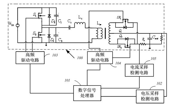
[0057] see figure 1 , the LLC resonant converter synchronous rectification digital control device includes a digital signal processor DSP (101), a primary side high-frequency drive circuit (103), a current sampling detection circuit (113), a voltage sampling detection circuit (102) and a secondary-side high-frequency drive circuit (104), characterized in that the digital signal processor DSP (101) passes through the primary-side high-frequency drive circuit (103), the current sampling detection circuit (105), and the voltage sampling detection circuit respectively. The circuit (102) and the secondary high-frequency drive circuit (104) are connected to the controlled LLC synchronous rectification resonant converter circuit (100).

[0058] The digital signal processor (101) judges the operating area of ​​the circuit according to the output voltage fed back by the voltage sampling detection circuit (102), and changes the values ​​of the two on-chip period registers respectively a...

Embodiment 2

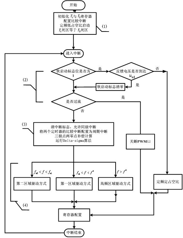
[0070] see image 3 , the digital control method of the LLC resonant converter synchronous rectification circuit adopts the above-mentioned control device to control the above-mentioned circuit, and it is characterized in that the control steps are as follows:

[0071] (1) Initialize the digital signal processor (101) on-chip timer and , set it as compare interrupt, set the same dead time , the same high-frequency period register value , the same compare register value . through the appropriate and The value realizes the soft start of the circuit with high frequency and low duty cycle, and reduces the impact and electromagnetic interference on the circuit caused by variable frequency start. in The register output controls the primary side drive signal, The register output controls the secondary side drive signal.

[0072] (2) After entering the interrupt, judge whether the soft start of the circuit is over or whether the circuit is overcurrent. If the ci...


PUM


Abstract

The invention relates to a digital control device and method of an LLC (Logic Link Control) synchronous rectification resonant converter. The digital control device comprises a digital signal processor, a primary side high-frequency drive circuit, a current sampling detection circuit, a voltage sampling detection circuit and a secondary side high-frequency drive circuit. The digital control method comprises the step of: carrying out digital control on the LLC resonant converter by using a digital signal processing chip: when in light load, a secondary side synchronizing rectifier tube is switched on in advance, the problem of conduction loss of the synchronizing rectifier tube, caused by introducing a light load by the traditional control strategy, is effectively solved; and when in heavy load, a secondary side drive signal is immediately switched off according to circuit parameters, and an overcurrent protection circuit is designed for monitoring output overcurrent caused by smaller equivalent impedance when a working region is switched.

Description

technical field [0001] The invention belongs to the field of communication power supply and LED lighting, and in particular relates to a digital control device and method for an LLC synchronous rectification resonant converter, especially a control method for improving the loss of an LLC synchronous rectification resonant converter under a light load state. Background technique [0002] The traditional LLC resonant converter generates resonance through resonant inductor, resonant capacitor and transformer to realize soft switching. [0003] The working state of the LLC resonant converter can be divided into two areas: when the circuit works at light load or no load, the resonant converter operates in working area 1; when the circuit works at rated load or heavy load, the resonant converter operates in the working area area two. At this time, the fast recovery diode on the secondary side is turned on with zero current, which further improves the efficiency of the LLC convert...

Claims


Application Information

Patent Timeline
IPC IPC(8): H02M7/217
CPCY02B70/1441Y02B70/10
Inventor 廖文高艳霞刘攀杨郑浩
Owner SHANGHAI UNIV
Why Eureka
Try Eureka