RSSI (Received Signal Strength Indicator) circuit used for OLT (Optical Line Terminal) optical module in passive optical network

A passive optical network and optical module technology, which is applied in the direction of electrical components, electromagnetic wave transmission systems, transmission systems, etc., can solve the problems of undetectable, poor detection accuracy of burst optical packets, weak light and strong light detection, etc. problem, to achieve the effect of ensuring the detection accuracy and solving the large dynamic detection of RSSI

Active Publication Date: 2012-05-02
WUHAN HUAGONG GENUINE OPTICS TECH
View PDF6 Cites 9 Cited by
  • Summary
  • Abstract
  • Description
  • Claims
  • Application Information

AI Technical Summary

Problems solved by technology

[0004] In the optical module industry, the RSSI circuit diagram design scheme can be roughly divided into two categories, one is the single signal method, which uses a sampling resistor or a transimpedance amplifier. The disadvantage of this design is that the circuit detects optical power. The dynamic range of the camera is insufficient, and the detection of weak light and strong light cannot be considered at both ends
Another des

Method used


Image

  • RSSI (Received Signal Strength Indicator) circuit used for OLT (Optical Line Terminal) optical module in passive optical network
  • RSSI (Received Signal Strength Indicator) circuit used for OLT (Optical Line Terminal) optical module in passive optical network
  • RSSI (Received Signal Strength Indicator) circuit used for OLT (Optical Line Terminal) optical module in passive optical network

Examples


Embodiment Construction

[0019] In order to facilitate a further understanding of the circuit structure and achieved effects of the present invention, preferred embodiments are described in detail below in conjunction with the accompanying drawings.

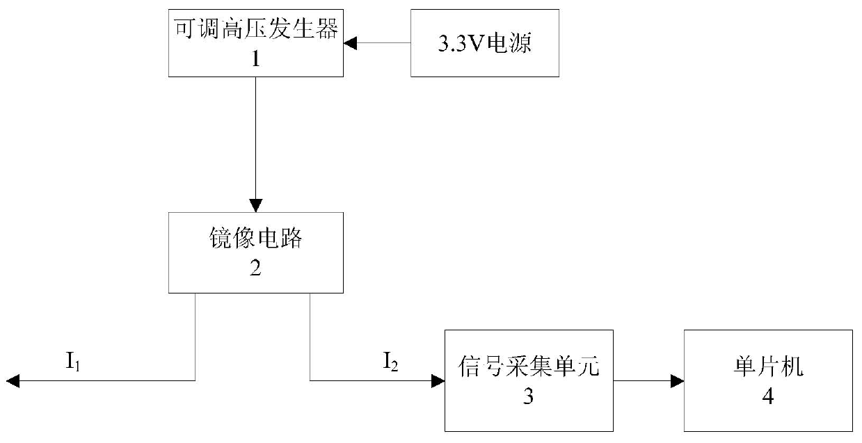
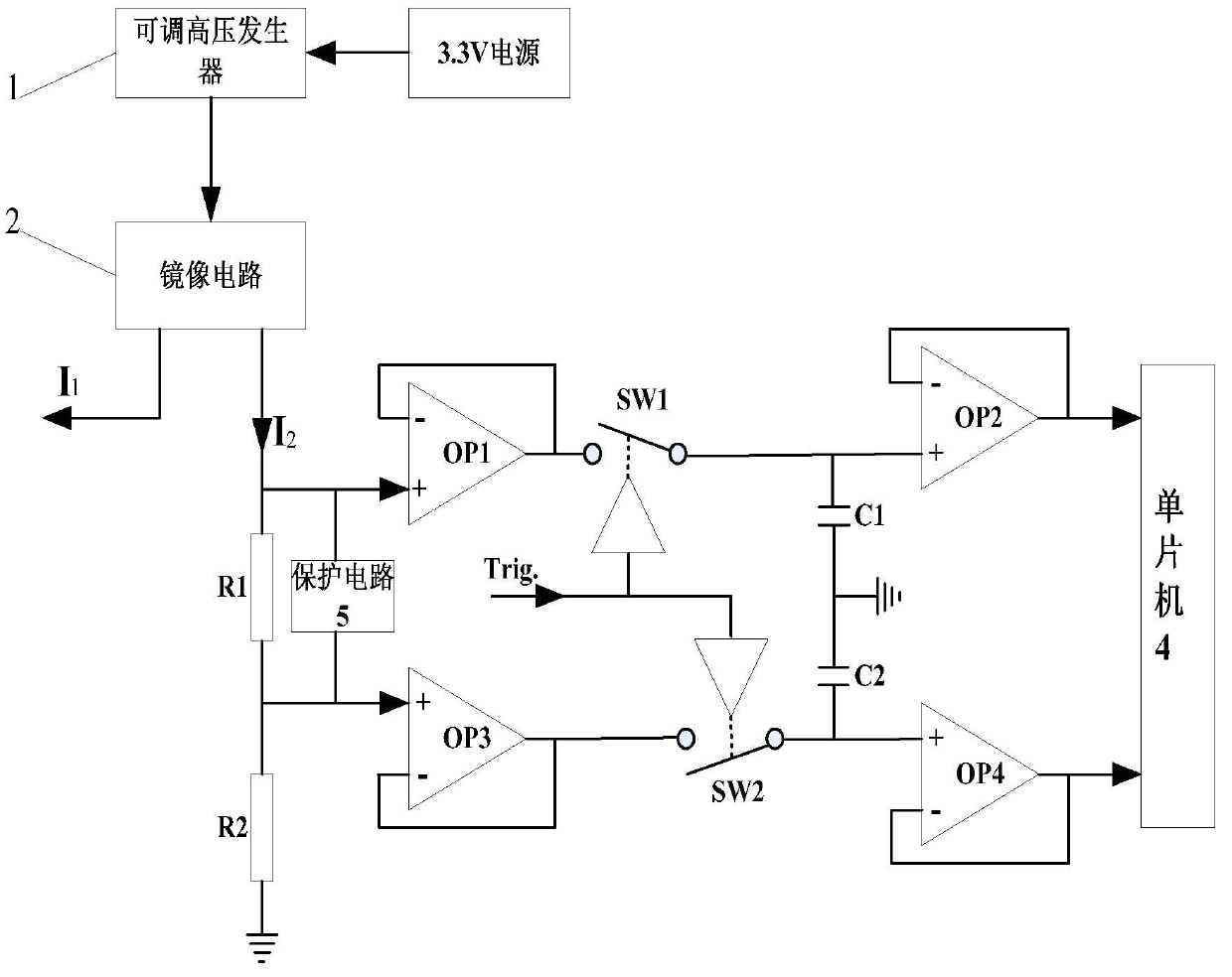
[0020] Such as figure 1 and figure 2 As shown, the RSSI circuit of the present invention includes an adjustable high-voltage generator 1 and a mirror circuit 2, the adjustable high-voltage generator 1 uses 3.3V DC as its power supply, and the adjustable high-voltage generator 1 outputs a DC voltage of tens of volts , the size of the high voltage is determined by the characteristics of the APD (avalanche photodiode) at the temperature at that time, and the specific adjustment of the high voltage can be adjusted with an adjustable resistor, a digital potentiometer or a single-chip microcomputer.

[0021] The output terminal of the adjustable high-voltage generator 1 is connected to the input terminal of the mirror circuit 2, and the mirror circuit 2 has ...


PUM


Abstract

The invention discloses an RSSI (Received Signal Strength Indicator) circuit used for an OLT (Optical Line Terminal) optical module in a passive optical network. The RSSI circuit comprises an adjustable high-voltage generator and a mirror image circuit, wherein the output end of the adjustable high-voltage generator is connected with the input end of the mirror image circuit; the mirror image circuit is provided with two output channels, i.e. a main channel and a secondary channel; the main channel outputs current I1 to provide reversed operating bias voltage to an avalanche photodiode of the OLT; the secondary channel outputs mirror current I2 and is connected with a signal acquisition unit; and the signal acquisition unit collects highlight and weak light signals and transmits the signals to a singlechip. The RSSI circuit has the outstanding advantage that a processing circuit can obtain a signal amplitude which is big enough no matter the weak light or the hightlight is detected, thereby solving the problem of big dynamic detection of the RSSI of the OLT module in a PON (Passive Optical Network), and ensuring the detection precision of the RSSI of the OLT module in the whole optical power zone.

Description

technical field [0001] The present invention relates to an RSSI (Received Signal Strength Indication, received signal strength indication) circuit of an optical module, in particular to an optical line terminal (Optical Line Terminal, OLT) RSSI circuit of the optical module. Background technique [0002] In the evolution of optical fiber communication access network, FTTH (fiber to the home) is the goal to be achieved in the next few years. Use a hair-thin optical fiber to meet the two-way information transmission of each user, whether it is making calls, transmitting data or watching videos, whether you are at home or in the office, all of this can be realized on a single optical fiber. [0003] At present, the optical fiber access network adopts a passive optical network (Passive Optical Network, PON): an optical fiber is led out in the office, and the optical signal sent from the office can be divided into 8 optical signals through an optical splitter. 16, ... 128, and...

Claims


Application Information

Patent Timeline
IPC IPC(8): H04B10/08H04B10/07
Inventor 钟春晖钟迪新
Owner WUHAN HUAGONG GENUINE OPTICS TECH
Why Eureka
Try Eureka