Magnetic resonance imaging device and magnetic resonance imaging method

A magnetic resonance imaging and nuclear magnetic resonance technology, which is applied in the direction of magnetic resonance measurement, measurement using nuclear magnetic resonance imaging system, measurement device, etc., can solve problems such as phase error signal intensity distribution, and achieve the effect of reducing image distortion

Active Publication Date: 2012-05-02
TOSHIBA MEDICAL SYST CORP
View PDF6 Cites 18 Cited by
  • Summary
  • Abstract
  • Description
  • Claims
  • Application Information

AI Technical Summary

Problems solved by technology

[0008] The above-mentioned phase error due to static magnetic field inhomogeneity varies depending on the signal intensity distribution of the imaging object and the spatial distribution of the static magnetic field inhomogeneity in the imaging area

Method used


Image

  • Magnetic resonance imaging device and magnetic resonance imaging method
  • Magnetic resonance imaging device and magnetic resonance imaging method
  • Magnetic resonance imaging device and magnetic resonance imaging method

Examples


no. 1 Embodiment approach

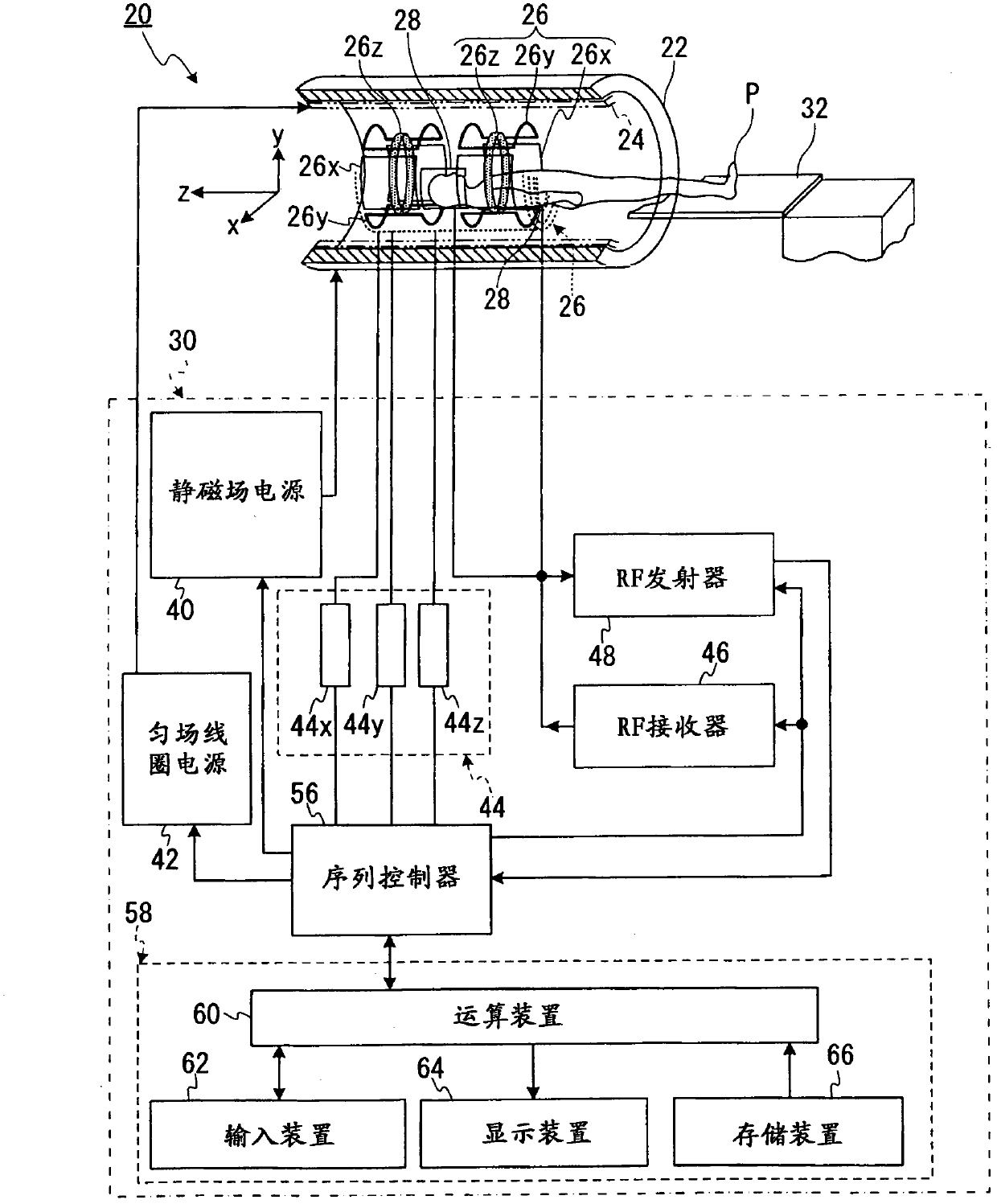
[0049] figure 1 It is a block diagram showing the overall configuration of the MRI apparatus 20 in the first embodiment. Such as figure 1 As shown, the MRI apparatus 20 has a cylindrical static magnetic field magnet 22 for forming a static magnetic field, a cylindrical shim coil 24 coaxially arranged inside the static magnetic field magnet 22, a gradient magnetic field coil 26, an RF coil 28, a control The apparatus 30 and the platen 32 on which the subject P is placed.

[0050] Here, as an example, the X-axis, Y-axis, and Z-axis perpendicular to each other of the device coordinate system are defined as follows. First, the static magnetic field magnet 22 and the shim coil 24 are arranged such that their axial directions perpendicularly cross the vertical direction, and the axial direction of the static magnetic field magnet 22 and the shim coil 24 is referred to as the Z-axis direction. In addition, let the vertical direction be the Y-axis direction, and the table 32 is arr...

no. 2 Embodiment approach

[0173] The MRI apparatuses of the second and third embodiments have the same apparatus configuration as the MRI apparatus 20 of the first embodiment. In the second embodiment, correction for uniformizing the static magnetic field based on the magnetic field correction map is not performed, and only phase error correction is performed. Hereinafter, the second embodiment will be described focusing on differences from the first embodiment.

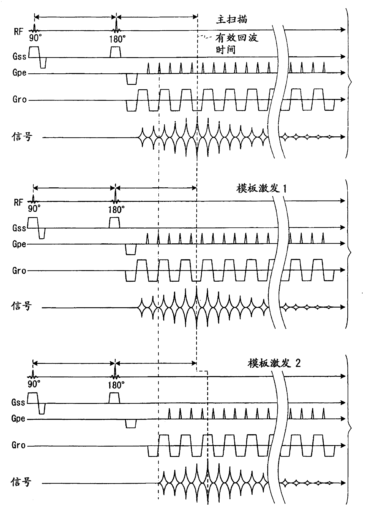
[0174] Figure 12 It is a time chart showing an example of pulse sequences of main scan and template excitation 1, 2' as single-shot EPI of the spin echo system in the second embodiment. Figure 12 The format of the middle, horizontal axis, etc. is the same as image 3 same, Figure 12 The main scan in the upper stage and the template excitation 1 in the middle stage are the same as the main scan and template excitation 1 in the first embodiment, respectively.

[0175] Figure 12 Among them, only the template shot 2' (TEMPLATE SHOT 2') i...

no. 3 Embodiment approach

[0193] In the third embodiment, as in the first embodiment, the correction for making the static magnetic field uniform and the correction for the phase error based on the magnetic field correction map are performed. In the third embodiment, three template excitations are performed. Hereinafter, the third embodiment will be described focusing on differences from the first embodiment.

[0194] Figure 14 It is a time chart showing an example of the pulse sequence of the template excitation 1, 2', 3 as the single-shot EPI of the spin echo system in the third embodiment. exist Figure 14 The format of the middle, horizontal axis, etc. is the same as image 3 same.

[0195] The pulse sequence of the main scan in the third embodiment is the same as the main scan in the first embodiment and the template excitation 1 in the third embodiment, so it is not shown in the figure.

[0196] Figure 14 The template shot 1 (TEMPLATE SHOT 1) shown in the above paragraph is the same as th...


PUM


Abstract

The invention provides a magnetic resonance imaging device and a megnetic resonance imaging method. According to one embodiment, an MRI device (20) includes a first collecting section, a second collecting section, and a correcting section (100). The first collecting section and the second collecting section generate a plurality of echo signals by executing an EPI echo-signal collecting sequence which involves the application of a phase-encoding-direction gradient magnetic field, and collect the echo signals respectively as first and second template data. The second collecting section collects the second template data after the collection of the first template data in accordance with a sequence in which the timing for starting the application of a read-out-direction gradient magnetic field is shifted from that at the time of collecting the first template data. The correcting section (100) corrects phase errors contained in the echo signals by using the first and second template data.

Description

technical field [0001] Embodiments of the present invention relate to a magnetic resonance imaging apparatus and a magnetic resonance imaging method. Background technique [0002] MRI is an imaging method in which nuclear spins of a subject placed in a static magnetic field are magnetically excited by an RF pulse of a Larmor frequency, and an image is reconstructed from an MR signal generated with the excitation. In addition, the above-mentioned MRI means magnetic resonance imaging (Magnetic Resonance Imaging), RF pulse means radio frequency pulse, and MR signal means nuclear magnetic resonance signal (nuclear magnetic resonance signal). [0003] In MRI, there is an imaging method called EPI (echo planar imaging: echo planar imaging). EPI is a kind of high-speed imaging method, which is a method of collecting MR signals by continuously inverting (reversing) a gradient magnetic field (gradient magnetic field) at high speed for one nuclear magnetic excitation, and continuousl...

Claims


Application Information

Patent Timeline
Patent Type & Authority Applications(China)
IPC IPC(8): A61B5/055G01R33/54
CPCG01R33/5616G01R33/56554
Inventor 草原博志葛西由守待井丰
Owner TOSHIBA MEDICAL SYST CORP
Why Eureka
Try Eureka