Shock-absorbing steering device

A technology of steering device and shock absorption, which is applied in the direction of steering column, steering control, steering mechanism, etc., can solve the problems of limited degree of freedom, failure to use, and inability to reduce torque, etc., to improve shock absorption performance, easy absorption performance, and excellent performance effect

Active Publication Date: 2012-05-02
NSK LTD
View PDF12 Cites 19 Cited by
  • Summary
  • Abstract
  • Description
  • Claims
  • Application Information

AI Technical Summary

Problems solved by technology

In this case, if Figure 23 ~ Figure 24 As shown, with the structure in which the energy absorbing member 36 is provided between the steering column 6b and the vehicle body 37 provided on the upper side of the steering column 6b, the above-mentioned moment cannot be reduced, and the instability of the energy absorbing performance cannot be prevented.
In other words, in Figure 23 ~ Figure 24 In the structure shown, when it is desired to suppress the above-mentioned moment to a small value and prevent instability of the energy absorption performance, the structure in which the fastening rod 27 is arranged on the lower side of the steering column cannot be adopted, and the degree of freedom of design is limited.
Moreover, in Figure 21 ~ Figure 24 In the structure shown, the support pin 38 and the holding case 39 are required as dedicated parts for installing the energy absorbing member 36, so the cost increase cannot be avoided.

Method used


Image

  • Shock-absorbing steering device
  • Shock-absorbing steering device
  • Shock-absorbing steering device

Examples


no. 1 Embodiment approach

[0078] refer to Figure 1 to Figure 9 An example of the first embodiment of the present invention will be described. The impact-absorbing steering device of this example includes: an inner column 14a; an outer column 13a; a steering shaft 5b; a pair of clamped wall portions 11a; a pair of front and rear direction long holes 28; a support bracket 10a; The direction long holes 26a, 26b; the fastening rod 27a; the cam device 32a constituting the fixing mechanism; and, the energy absorbing member 36a. However, in the definition of the present invention, the long hole 28 in the front-rear direction corresponds to the first through hole, and the long holes 26a, 26b in the vertical direction correspond to the second through hole. The shapes of these first and second through holes can be changed depending on whether the steering device is equipped with a telescoping mechanism and / or a tilting mechanism. In a structure that does not have these mechanisms, for example, one or both of ...

no. 2 Embodiment approach

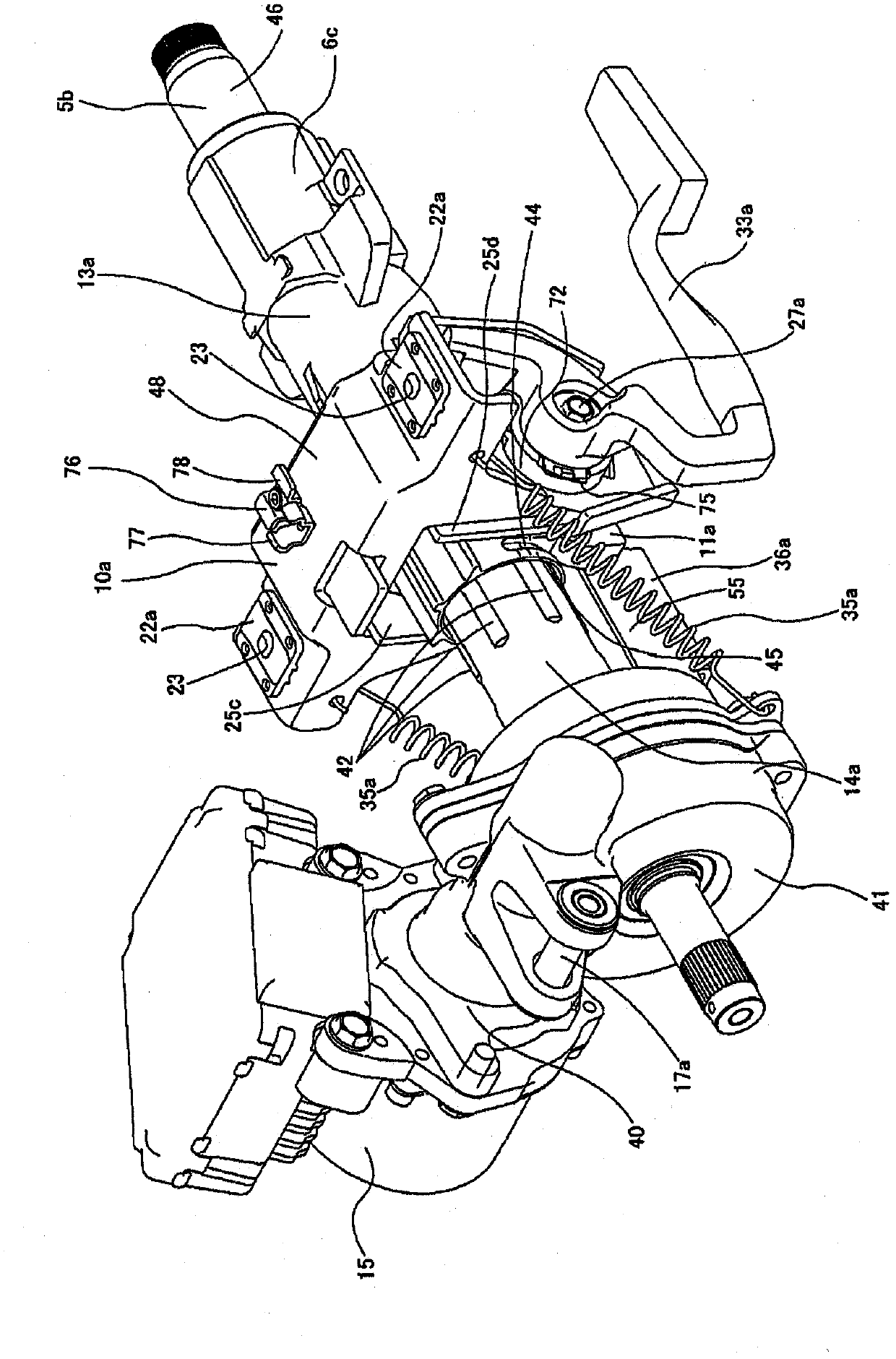
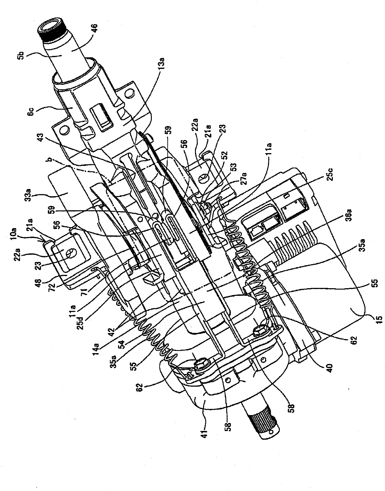
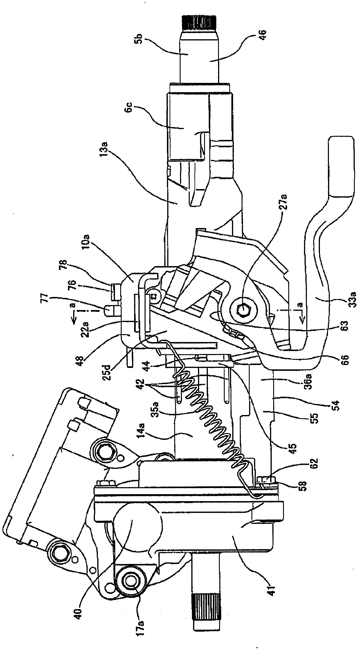
[0104] refer to Figure 10 ~ Figure 17 An example of the second embodiment of the present invention will be described. The impact-absorbing steering device of the second embodiment differs from the first embodiment only in the structure for absorbing the impact energy at the time of the secondary collision, that is, the structure of the energy absorbing member. Therefore, the description of the same structure as the first embodiment is omitted or simplified, and the energy absorbing member which is the characteristic part thereof will be described below. In addition, the description of this example is also based on the structure in which the tightening rod is arranged below the outer column, but this aspect can of course also be applied to the structure in which the tightening rod is arranged above the outer column. In this case, similarly to the description in the first embodiment, it is only necessary to reverse the vertical direction regarding the members and the positiona...


PUM


Abstract

In order to configure a shock-absorbing steering device which achieves excellent performance at a low-cost whilst maintaining design freedom, the device is provided with: a tightening rod (27a) which is displaced forward, together with an outer column (13a), during secondary impact; and energy absorbing members (36a, 36b) which are provided in the gap between a locking pin (63) or a housing (16) not displaced forward during secondary impact, are formed from members which plastically deform in accordance with the forward displacement of the outer column (13a) which occurs during secondary impact, and which absorb part of the impact energy by means of the relative movement of the plastic deformation. Part of the energy absorbing members (36a, 36b) is fixed to the tightening rod (27a), and the plastic deformation of the members (36a, 36b) is limited in the width-ways direction by a pair of held wall sections (11a) in the outer column (13a).

Description

technical field [0001] The present invention relates to an improvement of an impact-absorbing steering device capable of displacing the steering wheel forward while absorbing the impact energy applied to the steering wheel from the driver's body in the event of a collision accident. Background technique [0002] Such as Figure 18 As shown, the steering device for a motor vehicle is configured in the following manner: the rotation of the steering wheel 1 is transmitted to the input shaft 3 of the steering gear unit 2, and as the input shaft 3 rotates, a pair of left and right tie rods 4 are pushed and pulled, and the front The wheels are given the steering angle. Therefore, the steering wheel 1 is supported and fixed to the rear end portion of the steering shaft 5 , and the steering shaft 5 is rotatably supported by the steering column 6 while penetrating the cylindrical steering column 6 in the axial direction. Further, the front end of the steering shaft 5 is connected to...

Claims


Application Information

Patent Timeline
Patent Type & Authority Applications(China)
IPC IPC(8): B62D1/19B62D1/18B62D5/04
CPCB62D1/195B62D1/184F16F7/123
Inventor 成田典智山本恒
Owner NSK LTD
Why Eureka
Try Eureka