Sensor device for magnetic particles with a high dynamic range

A technology of sensor equipment and magnetic particles, applied in the direction of instruments, scientific instruments, material analysis through electromagnetic means, etc.

Inactive Publication Date: 2012-05-02
KONINKLIJKE PHILIPS ELECTRONICS NV
View PDF4 Cites 7 Cited by
  • Summary
  • Abstract
  • Description
  • Claims
  • Application Information

AI Technical Summary

Problems solved by technology

The difficulty encountered with this and similar methods is that in practice they have to deal wi

Method used


Image

  • Sensor device for magnetic particles with a high dynamic range
  • Sensor device for magnetic particles with a high dynamic range
  • Sensor device for magnetic particles with a high dynamic range

Examples


Embodiment Construction

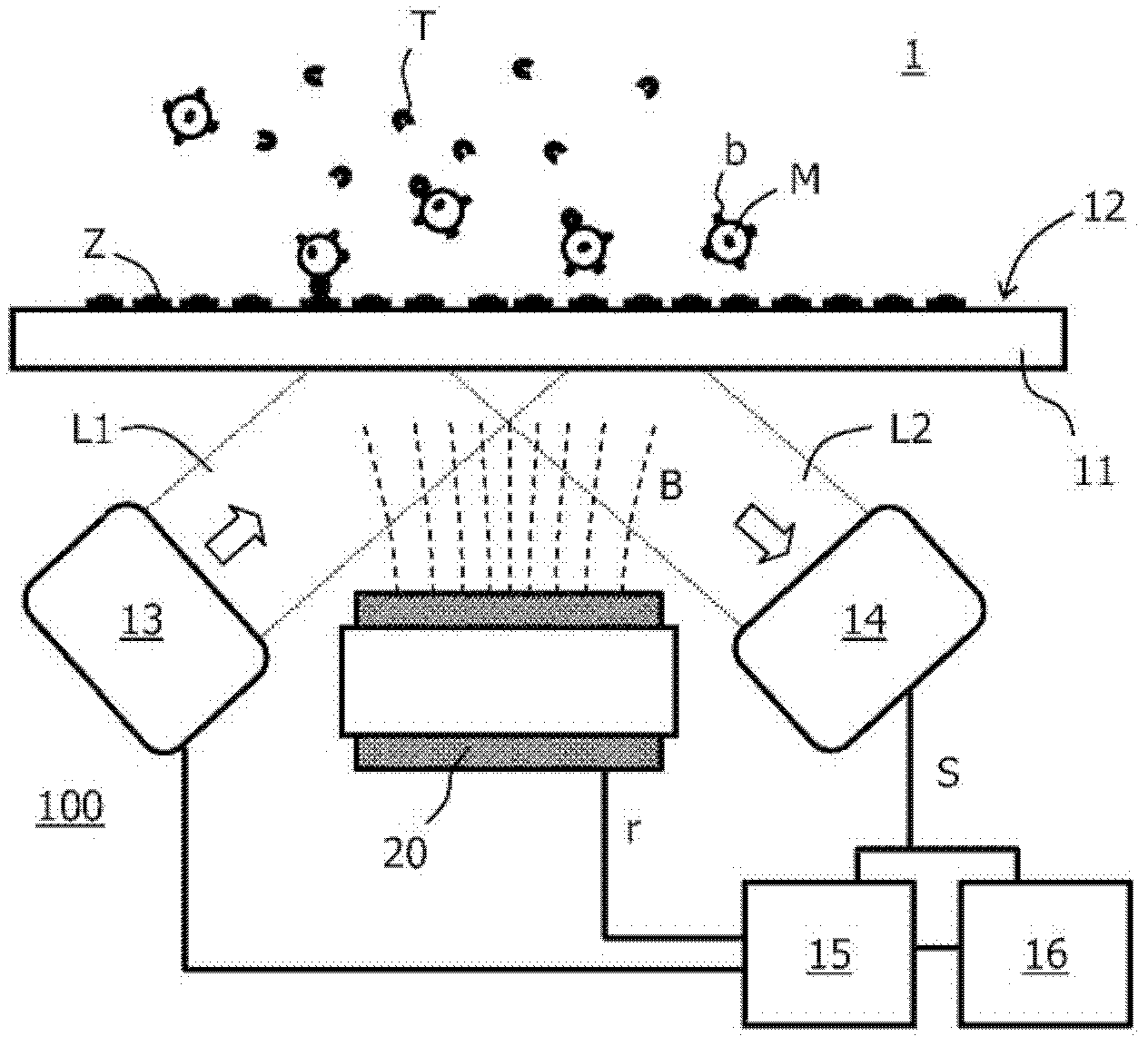
[0038] An important topic in the field of molecular diagnostics (MD) is the development of instruments for providing rapid diagnosis at point-of-care (POC) and in emergency situations. The primary requirements for an MD platform are speed of diagnosis, adequate sensitivity, and ease of use. In addition, disposables with microfluidic channels are preferred to increase the flexibility of the platform for a large number of manufacturers.

[0039] For many applications, the diagnostic method of choice is based on performing immunoassays. Here, possible detection methods include, inter alia, frustrated total internal reflection (FTIR) using magnetic labels and confocal fluoroscopy using molecular fluorescent labels. While both methods are sufficiently sensitive to detect small changes in labelling, robustness must be ensured for all physical aspects that can affect the inherent biochemical properties of the assay components. By using superparamagnetic beads, the kinetics of the a...


PUM


Abstract

The invention relates to a method and a sensor device (100) for the detection of magnetic particles (M) in a sample. The magnetic particles (M) can bind to binding sites (Z) at a binding surface (12), where they can be detected by a detection unit (13, 14). A controller (15) is provided for controlling magnetic attraction (B) of the magnetic particles (M) towards the binding surface (12) in dependence on the detection signal (S) of the detection unit (14) in such a way that rotational relaxation conditions for the magnetic particles (M) are changed. In particular, this change can be controlled to maximize the binding of magnetic particles (M) to the binding surface (12) within a given measurement time. The change can for example be achieved by repeatedly switching the magnetic attraction off for prolonged periods, giving the magnetic particles (M) better chances to orient properly with respect to the binding surface (12).

Description

technical field [0001] The invention relates to a method and a sensor device for the detection of magnetic particles in a sample, wherein the particles can in particular bind to binding sites on a binding surface. Furthermore, the invention relates to the use of such devices. Background technique [0002] In US6991938 an assay assay for the quantitative determination of components bound to solids is described. The detection signal is continuously monitored and used to infer the amount of constituents in the sample. The difficulty encountered with this and similar methods is that in practice they have to deal with a large dynamic range of unknown concentrations, which generally covers at least three decades. Contents of the invention [0003] Based on this background technology, the purpose of the present invention is to provide a means for accurate detection of targeted particles in a sample within a wide dynamic concentration range. [0004] This object is achieved by ...

Claims


Application Information

Patent Timeline
IPC IPC(8): G01N33/543
CPCG01N27/745G01N33/54326G01N21/552
Inventor C·B·克劳斯
Owner KONINKLIJKE PHILIPS ELECTRONICS NV
Why Eureka
Try Eureka