Temper mill on-line roll changing cylinder synchronous control system and control method
A technology of synchronous control and leveling machine, applied in mechanical equipment, fluid pressure actuators, servo motors, etc., can solve problems such as poor synchronization accuracy, and achieve the effect of improving system accuracy and performance, high precision, and fast response
- Summary
- Abstract
- Description
- Claims
- Application Information
AI Technical Summary
Problems solved by technology
Method used
Image

Examples
Embodiment Construction
[0044] The technical solution of the present invention will be described in detail below in conjunction with the accompanying drawings and specific embodiments to further understand the purpose, solution and effect of the present invention, but it is not intended to limit the scope of protection of the appended claims of the present invention.
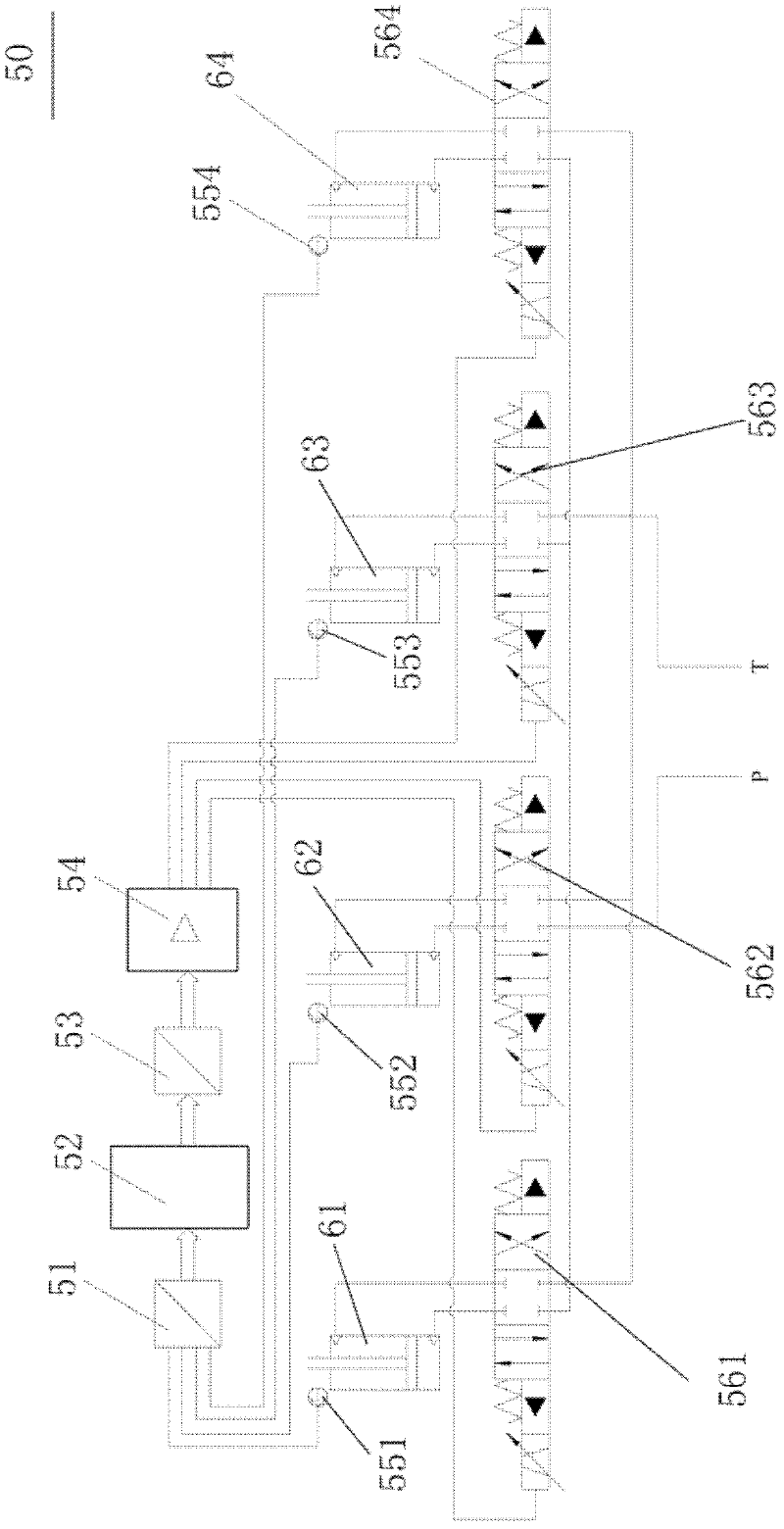
[0045] refer to figure 2 The structural block diagram of the online roll changing cylinder synchronous control system of the temper mill of the present invention, as shown in the figure, the online roll changing cylinder synchronous control system 50 of the temper mill of the present invention is combined with the hydraulic system of the online roll changing of the temper mill, so The hydraulic system includes a plurality of hydraulic cylinders 61, 62, 63, 64 arranged in parallel, the control system 50 includes a plurality of hydraulic cylinder position detection modules 551, 552, 553, 554, an A / D input module 51, a PLC controller 52, ...
PUM
 Abstract
Description
Claims
Application Information
 - Generate Ideas
- Intellectual Property
- Life Sciences
- Materials
- Tech Scout
- Unparalleled Data Quality
- Higher Quality Content
- 60% Fewer Hallucinations
Browse by: Latest US Patents, China's latest patents, Technical Efficacy Thesaurus, Application Domain, Technology Topic, Popular Technical Reports.
© 2025 PatSnap. All rights reserved.Legal|Privacy policy|Modern Slavery Act Transparency Statement|Sitemap|About US| Contact US: help@patsnap.com